
Pulsed-field differential mobility analyzer system and method for separating particles and measuring shape parameters for non-spherical particles

a technology of differential mobility analyzer and particle separation, which is applied in the direction of particle separator tubes, material analysis, instruments, etc., can solve the problems of inability to dimensionally characterize by just one length scale, time-consuming operations, and poor sampling methods, and achieve the effect of rapid rise and fall

Active Publication Date: 2017-06-13
UNIV OF MARYLAND
View PDF34 Cites 5 Cited by
  • Summary
  • Abstract
  • Description
  • Claims
  • Application Information

AI Technical Summary

Benefits of technology

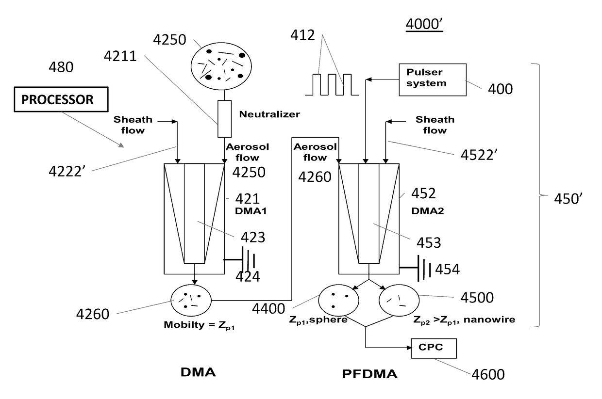
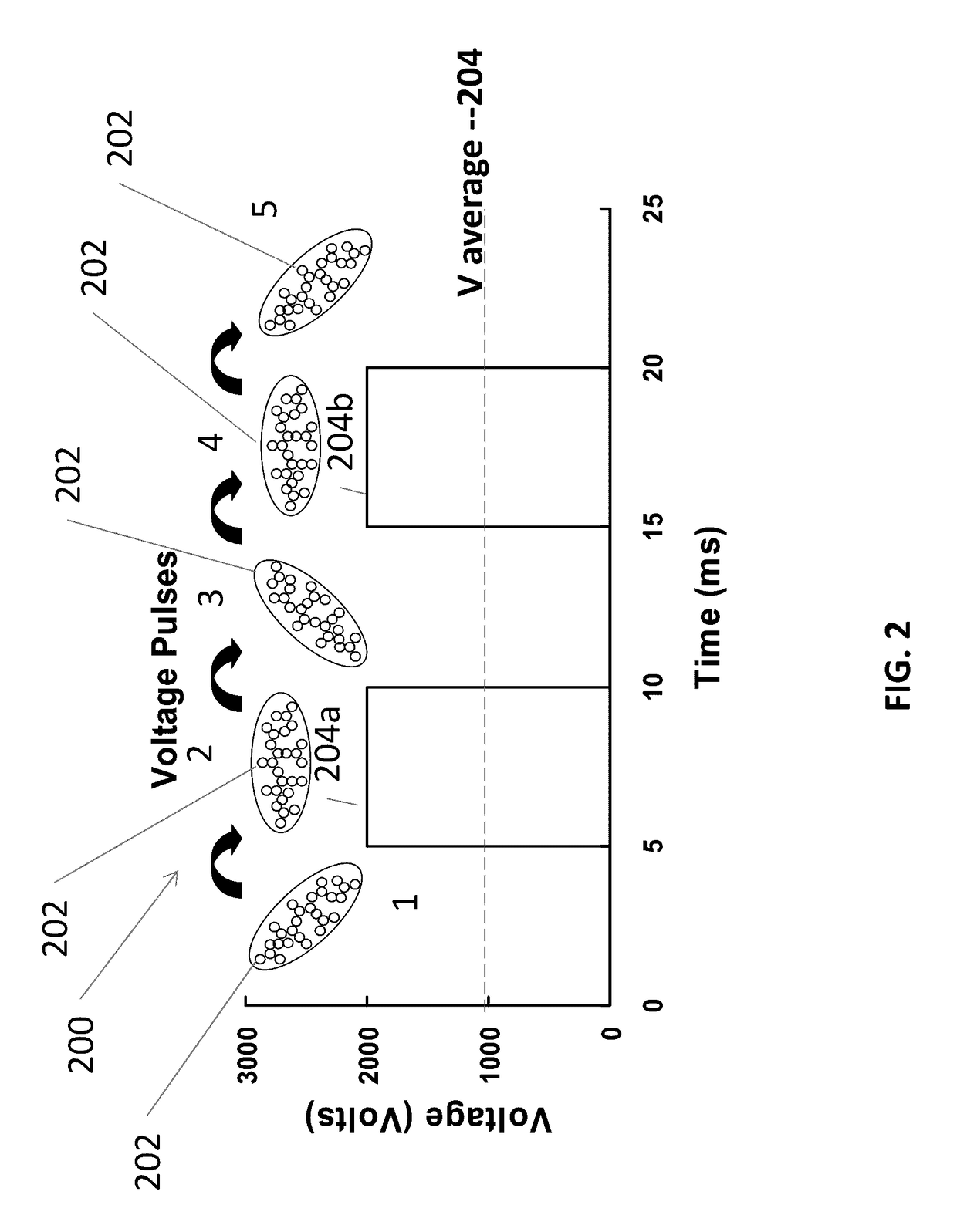
[0014]The embodiments of the present disclosure relate to a method for operating a pulse field differential mobility analyzer (PFDMA) system, and a pulse field differential mobility analyzer (PFDMA) system that executes at least passing an aerosol through a PFDMA system; creating a pulse electric field in the PFDMA via a pulser system; executing processor software to implement scanning as voltage steps of DC voltage from the pulser system; and generating a square electrical pulse with rapid rise and fall, and small drop off over the range of voltages of interest via the pulser system.

Problems solved by technology

The common feature of all these materials is that they are non-spherical and thus cannot be dimensionally characterized by just one length scale.
However, in these off-line methods, good sampling methods and time-consuming operations are needed for a precise distribution measurement.
One of the major challenges in particle online measurement is to extend the dimensionality measurement beyond the assumption of spherical symmetry.

Method used


Image

  • Pulsed-field differential mobility analyzer system and method for separating particles and measuring shape parameters for non-spherical particles
  • Pulsed-field differential mobility analyzer system and method for separating particles and measuring shape parameters for non-spherical particles
  • Pulsed-field differential mobility analyzer system and method for separating particles and measuring shape parameters for non-spherical particles

Examples


Embodiment Construction

[0044]For the purposes of promoting an understanding of the principles of the present disclosure, reference will now be made to the exemplary embodiments illustrated in the drawings, and specific language will be used to describe the same. It will nevertheless be understood that no limitation of the scope of the present disclosure is thereby intended. Any alterations and further modifications of the inventive features illustrated herein, and any additional applications of the principles of the present disclosure as illustrated herein, which would occur to one skilled in the relevant art and having possession of this disclosure, are to be considered within the scope of the present disclosure.

[0045]The word “exemplary” is used herein to mean “serving as an example, instance, or illustration.” Any embodiment described herein as “exemplary” is not necessarily to be construed as preferred or advantageous over other embodiments.

[0046]It is to be understood that the method steps described ...


PUM


Abstract

A method for extracting shape information for particles with similar shape and corresponding system of a tandem differential mobility analyzer (DMA) and pulse field differential mobility analyzer (PFDMA) system, that executes at least generating a steady state aerosol concentration; passing aerosol flow from the aerosol concentration thru a bipolar charger to produce a known charge distribution; passing aerosol thru a DMA with set sheath and aerosol flows and a set voltage to generate a mono-mobility aerosol; passing mono-mobility aerosol thru a PFDMA system; and measuring mobility as a function of electric field by varying the duty cycle of the pulse in the PFDMA system. Alternatively, the method and system relate to separating particles with different shapes by adjusting the duty cycle of the pulse to reach a higher or lower electric field than in the DMA in which the mono-mobility aerosol was generated; and separating particles based on shape.

Description

CROSS-REFERENCE TO RELATED APPLICATIONS[0001]This application claims the benefit of, and priority to, U.S. Provisional Patent Application 61 / 934,553 “DEVELOPMENT OF A PULSED-VOLTAGE DIFFERENTIAL MOBILITY ANALYZER”, by M. Zachariah et al., filed on Jan. 31, 2014, the entire contents of which are incorporated herein by reference.GOVERNMENT SUPPORT[0002]This invention was made with U.S. government support under 70NANB9H9199 awarded by the National Institute of Standards and Technology (NIST). The U.S. government has certain rights in this invention.BACKGROUND[0003]1. Technical Field[0004]This disclosure relates to differential mobility analyzers and more particularly to differential mobility analyzers that yield a mobility-equivalent spherical diameter.[0005]2. Description of Related Art[0006]Nanomaterials are widely applied and studied in medicine, electronics, biomaterials and environmental science. Effective measurement and accurate characterization of nanomaterials play a critical ...

Claims


Application Information

Patent Timeline
Patent Type & Authority Patents(United States)
IPC IPC(8): H01J49/00G01N15/02
CPCG01N15/0266G01N2015/0277G01N2015/0288G01N2015/0294
Inventor ZACHARIAH, MICHAEL R.LI, MINGDONGMULHOLLAND, GEORGE W.
Owner UNIV OF MARYLAND
Learn More