DC inductor

a technology of inductors and inductors, applied in the direction of transformers/inductance details, inductances, inductances with magnetic cores, etc., can solve the problems of mechanical failure of the attachment of permanent magnets, and achieve the effect of saving the production of inductors

Active Publication Date: 2011-02-15
ABB (SCHWEIZ) AG
View PDF13 Cites 10 Cited by
  • Summary
  • Abstract
  • Description
  • Claims
  • Application Information

AI Technical Summary

Benefits of technology

An advantage of the DC inductor of the invention is that the same basic core structure can be used for different ratings. The length of the at least one supporting member can be changed, which allows changing the number of permanent magnets used. The supporting member further affects the inductance of the inductor and can be varied to achieve a desired inductance value. Further, the one or more magnetic slabs that are in the core structure can be modified in various ways. The magnetic slabs are used to provide magnetic gaps to the main magnetic path. The length of this gap can be adjusted with differing slabs having different properties. Further the slab can be used to provide non-uniform magnetic gaps providing differing properties for the DC inductor.
Thus the present invention gives the possibility of using basic core structure that can be modified depending on the application. This leads to considerable savings in production of inductors, since only the commonly used forms of the inductor core need to be specifically structured for the intended use.

Problems solved by technology

The current that may cause de-magnetization may be a result of a malfunction in the apparatus to which the DC inductor is connected.
The attachments of the permanent magnets are vulnerable to mechanical failures since the permanent magnets are merely attached to one or two surfaces.
One of the problems associated with the prior art structures relates thus to a possibility of modifying the same core structure for different current levels or purposes.

Method used


Image

  • DC inductor
  • DC inductor
  • DC inductor

Examples


first embodiment

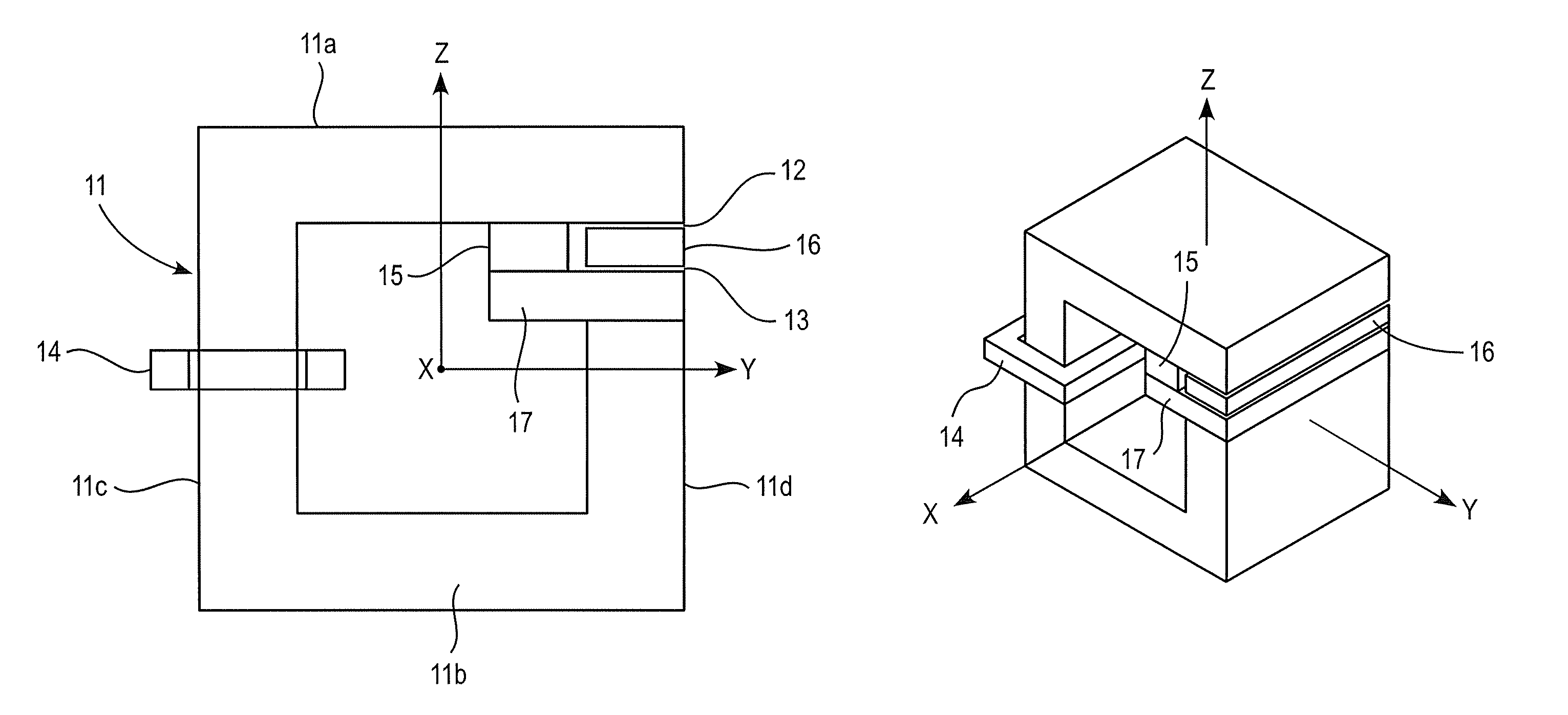
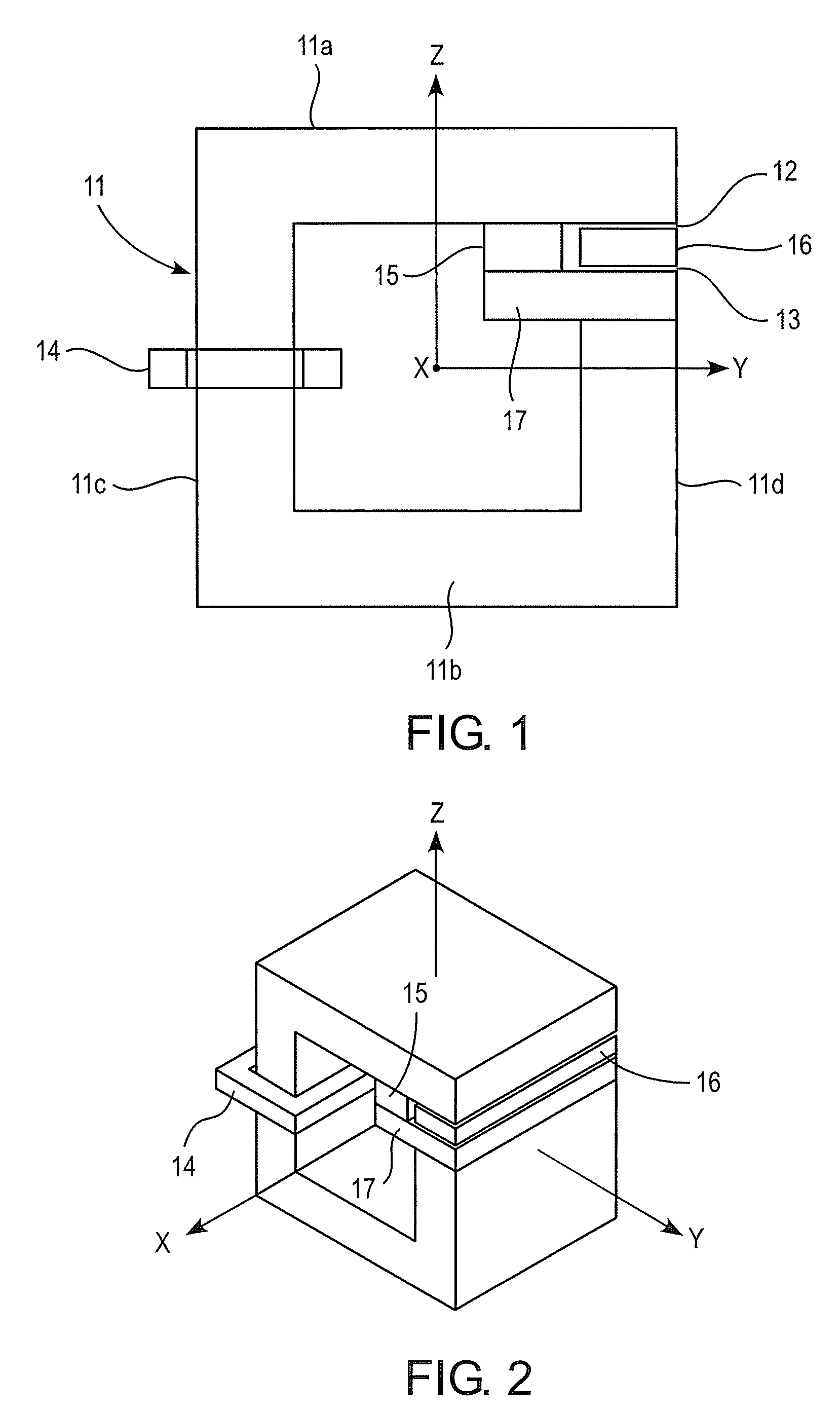
FIG. 1 shows the DC inductor according to the present invention. The core structure 11 is formed of a magnetic material, i.e. material that is capable of leading a magnetic flux. The material can be for example laminated steel commonly used in large inductors and as stator plates in motors, soft magnetic composite or iron powder.

The DC inductor of the invention comprises at least one coil 14 inserted on the core structure and one or more magnetic gaps 12, 13. The coil is typically wound on a bobbin and then inserted on the core structure in a normal manner. Alternatively, the coil can be wound directly to the core without a bobbin. The gaps are formed on the main magnetic path, by which it is referred to the magnetic path the magnetic flux of the coil flows. In the present invention, at least one of the possibly multiple magnetic gaps are formed by using magnetic slabs. In the embodiment of FIG. 1, the magnetic slab 16 is a separate piece that can be inserted into the core structure...

third embodiment

FIG. 6 shows the DC inductor according to the present invention. In this embodiment, two supporting members 33, 34 are supporting two permanent magnets 35, 36. The supporting members extend parallel to the core structure and inside the core structure. In this embodiment, the supporting members are also extended to outside of the core structure to hold other permanent magnet outside of the core structure.

The supporting members are extending from one leg of the core structure as shown in FIG. 6. The magnetic slab which produces one or more magnetic gaps is located according to the invention between the permanent magnets 35, 36 and the supporting members 33, 34.

FIG. 6 indicates the flux paths of the fluxes produced by the coil 38 and the permanent magnets 35, 36. The directions of the fluxes oppose each other, and the flux generated by the coil travels through the magnetic slab 37 while the flux of the permanent magnets flows through the supporting members 33, 34. Thus in the normal op...

fourth embodiment

FIG. 8 shows the DC inductor according to the present invention. In this embodiment the core structure comprises three legs 41, 42 and 43 and is basically an I-W core. The I-part of the core is situated on the top of the W-core, with the supporting member arranged on the center leg 43. Supporting member 44, which extends in parallel relationship with the core structure, further holds the permanent magnets 45, 46. The permanent magnets are between the supporting member and the core structure, especially the underside of the I-core.

In the embodiment shown in FIG. 8, the supporting member holds both the permanent magnets and the magnetic slab. The magnetic slab is used to form the magnetic gaps 47 to the center leg of the core structure.

The embodiment of FIG. 8 can be further modified by substituting the I-part with a T-part. That is to say that the magnetic slab of FIG. 8 is attached or made uniform with the I-part to produce the T-part. In this modification, the supporting member is ...


PUM

PropertyMeasurementUnit
magnetic gapsaaaaaaaaaa
magnetizationaaaaaaaaaa
magneticaaaaaaaaaa

Abstract

A DC inductor comprising a core structure (11) comprising one or more magnetic gaps (12, 13), a coil (14) wound on the core structure (11), at least one permanent magnet (15) positioned in the core structure, the magnetization of the permanent magnet (15) opposing the magnetization producible by the coil (14). The DC inductor further comprises at least one magnetic slab (16) inserted to the core structure which forms the one or more magnetic gaps (12, 13), at least one supporting member (17) made of magnetic material extending from the core structure inside the core structure and supporting the at least one permanent magnet (15), and that the at least one supporting member (17) is arranged to form a magnetic path for the at least one permanent magnet.

Description

FIELD OF THE INVENTIONThe present invention relates to a DC inductor, and particularly to a DC inductor having at least one permanent magnet arranged in the core structure of the inductor.BACKGROUND OF THE INVENTIONA major application of a DC inductor as a passive component is in a DC link of AC electrical drives. Inductors are used to reduce harmonics in the line currents in the input side rectifier system of an AC drive.The use of permanent magnets in the DC inductors allows minimizing the cross-sectional area of the inductor core. The permanent magnets are arranged to the core structure in such a way that the magnetic flux or magnetization produced by the permanent magnets is opposite to that obtainable from the coil wound on the core structure. The opposing magnetization of coil and permanent magnets makes the resulting flux density smaller and enables thus smaller cross-sectional dimensions in the core to be used.As is well known, permanent magnets have an ability to become dem...

Claims


Application Information

Patent Timeline
Patent Type & Authority Patents(United States)
IPC IPC(8): H01F21/00H01F27/24H01F17/06
CPCH01F3/14H01F27/385H01F37/00H01F2003/103
Inventor VIITANEN, TEROPIETERIS, PAULIUSHAUTAKORPI, ESA
Owner ABB (SCHWEIZ) AG
Why Eureka
Try Eureka