Optical receiver for visible light communication and light communication system using the same

a technology of optical receiver and visible light, applied in the field of light communication, can solve the problems of difficult to determine the accuracy of the aim and perform any immediate reaction to adjust the position of the device, interference problems, and the heavy influence of sunlight on optical receivers in the vlc system, so as to reduce the restriction of use and avoid the occurrence of erroneous operations

Inactive Publication Date: 2011-02-15
SAMSUNG ELECTRONICS CO LTD
View PDF3 Cites 22 Cited by
  • Summary
  • Abstract
  • Description
  • Claims
  • Application Information

AI Technical Summary

Benefits of technology

[0010]Accordingly, the present invention has been made in part to solve at least some of the above-mentioned problems occurring in the prior art. Therefore, one of the many aspects of the present invention is to provide an optical receiver for a visible light communication (VLC) system, which can minimize restrictions on use due to environmental conditions, as well as the occurrence of erroneous operations.

Problems solved by technology

However, conventional IR communication systems have a problem in that the emission characteristics of IR rays require aiming the communication path of the devices for efficient communication, and that the invisibility of emitted light makes it difficult to determine the accuracy of the aim and perform any immediate reaction to adjust the position of a device.
However, conventional optical receivers used for visible light communication systems have a problem in that because they employ visible light for communication, the wavelength band of which overlaps and has interference problems with many of the wavelength bands of light commonly encountered in daily life.
In particular, such optical receivers in a VLC system are heavily affected by sunlight.
In other words, in a conventional VLC system, when the optical receivers receive light in the overlapping wavelength bands, which are not employed by their communication systems, erroneous operation or inaccurate data detection may occur.
Furthermore, VLC communication systems may have to be used in a limited manner depending on the lighting of the environment.

Method used


Image

  • Optical receiver for visible light communication and light communication system using the same
  • Optical receiver for visible light communication and light communication system using the same
  • Optical receiver for visible light communication and light communication system using the same

Examples


Embodiment Construction

[0017]Hereinafter, exemplary embodiments of the present invention will be described in detail with reference to the accompanying drawings. The drawings are provided for illustrative purposes and a person of ordinary skill in the art understands and appreciates that the present invention is not limited to the drawings and descriptions herein. In the following description of the present invention, a detailed description of known functions and configurations incorporated herein is omitted to avoid obscuring the subject matter of the present invention with unnecessary description of such known functions and configurations.

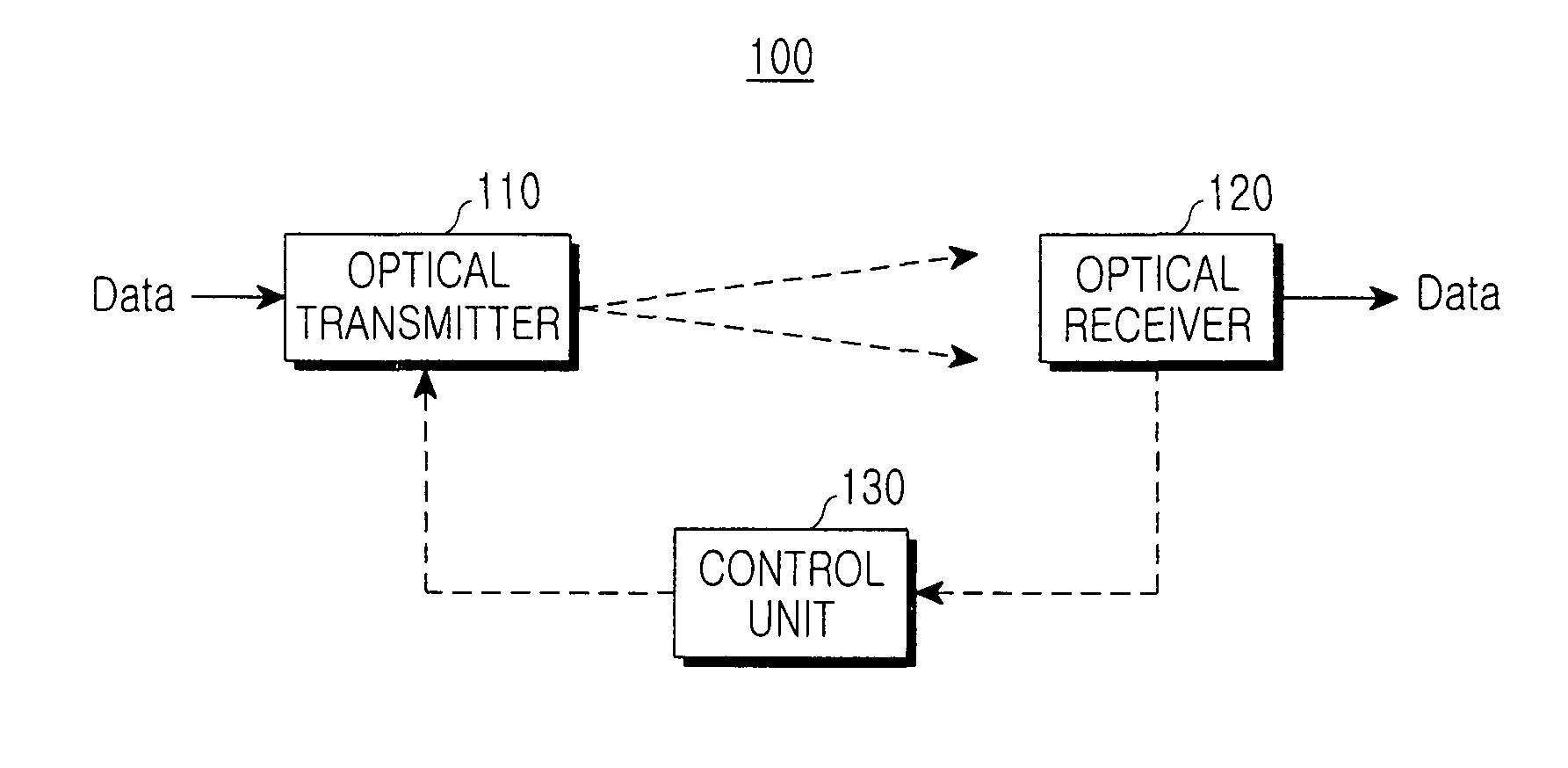
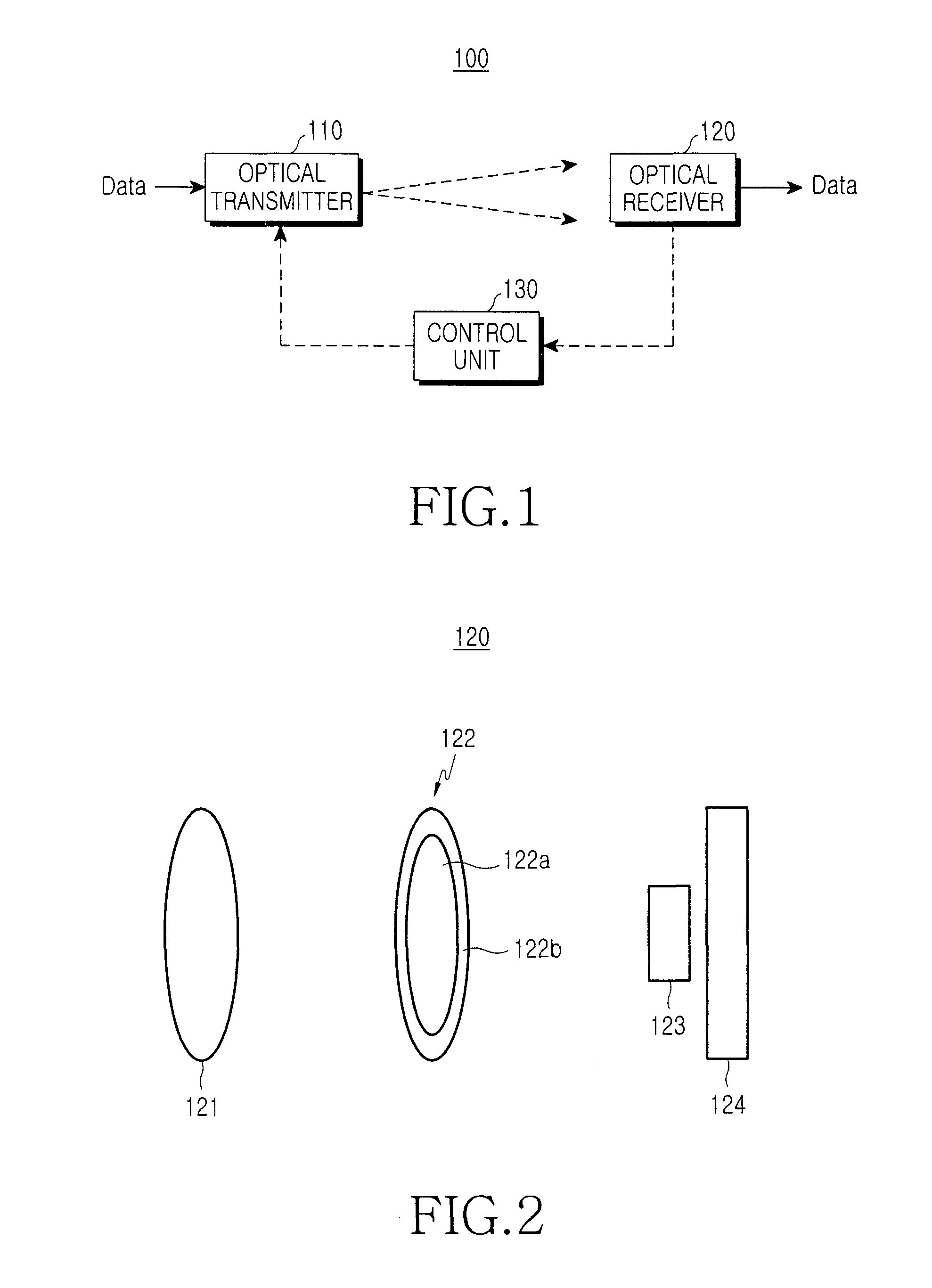
[0018]FIG. 1 shows a brief overview of the construction of a visible light communication system according to a first exemplary embodiment of the present invention, and FIG. 2 is a block diagram showing the brief construction of an optical receiver 120 shown in FIG. 1. Referring to FIG. 1, the visible light communication system 100 according to the present exemplary emb...


PUM


Abstract

An optical receiver for visible light communication includes a lens system for converging visible light for light communication and an optical filter for passing converged visible light to the optical receiver. A photoelectric transmission device detects data from visible light for light communication in a VLC system. An optical filter is positioned between the lens system and the photoelectric transmission device, the optical filter having a first film for transmitting visible light and a second film arranged / grown around the first film to transmit ultraviolet rays or infrared rays. A first optical detects data from visible light passing through the first film of the optical filter. A second optical detector detects the intensity of light transmitting the second film. The encoding, encoding rate or intensity of the optical transmitted signal can be adjusted in response to the detection of at least the second optical detector.

Description

CLAIM OF PRIORITY[0001]This application claims priority from application entitled “Optical Receiver for Visible Light Communication and Light Communication System Using the Same,” filed with the Korean Intellectual Property Office on Nov. 22, 2006 and assigned Serial No. 2006-115675, the contents of which are incorporated herein by reference in its entirety.BACKGROUND OF THE INVENTION[0002]1. Field of the Invention[0003]The present invention relates to light communication. More particularly, the present invention relates to an optical receiver for wireless light communication using light in the visible wavelength band.[0004]2. Description of the Related Art[0005]Conventional wireless light communication systems employ infrared wavelengths (i.e. IR communication systems), and their development has reached the level of Fast Infrared (FIR), with capacities of about 4 Mb / s (or more). Typical IR communication systems are commonly used purposes such as device control, as in the case of TV...

Claims


Application Information

Patent Timeline
Patent Type & Authority Patents(United States)
IPC IPC(8): H04B10/00
CPCH04B10/672H04B10/116G02B5/20H04B10/60
Inventor SON, JAE-SEUNGWON, EUN-TAEANN, JONG-HOON
Owner SAMSUNG ELECTRONICS CO LTD
Why Eureka
Try Eureka