Handle assembly for a cleaning appliance

a technology for cleaning appliances and handles, applied in the direction of closures, applications, closures, etc., can solve the problems of unnecessarily increasing losses, complicated or expensive manufacturing or repair, and/or easy damage to the wand cap, etc., to achieve simple and cheap manufacturing, easy and fast re-attachment, effective and simple

Inactive Publication Date: 2011-02-22
DYSON TECH LTD
View PDF15 Cites 16 Cited by
  • Summary
  • Abstract
  • Description
  • Claims
  • Application Information

AI Technical Summary

Benefits of technology

[0008]The handle assembly according the invention has the advantage of being effective but also simple and cheap to manufacture. Furthermore, it has the advantage that, should excessive force be applied to the wand cap, the wand cap is liable to become detached from the remainder of the handle assembly before it breaks. It can therefore be easily and quickly re-attached to the handle assembly without the use of specialist tools or replacement parts which is beneficial for the user.
[0009]In a preferred arrangement, retaining means are provided for retaining the wand cap in either the first position or the second position. Preferably, the retaining means comprise at least one profiled channel and a corresponding projection arranged to travel along the channel as the wand cap moves between the first and second positions. This arrangement is particularly effective and simple to achieve.

Problems solved by technology

A disadvantage of this type of arrangement is that, when the machine is used in upright mode, the incoming air still has to travel through the hose which unnecessarily increases losses.
In some cases, the wand cap has proved to be vulnerable to damage and / or complicated or expensive to manufacture or repair.

Method used


Image

  • Handle assembly for a cleaning appliance
  • Handle assembly for a cleaning appliance
  • Handle assembly for a cleaning appliance

Examples


Embodiment Construction

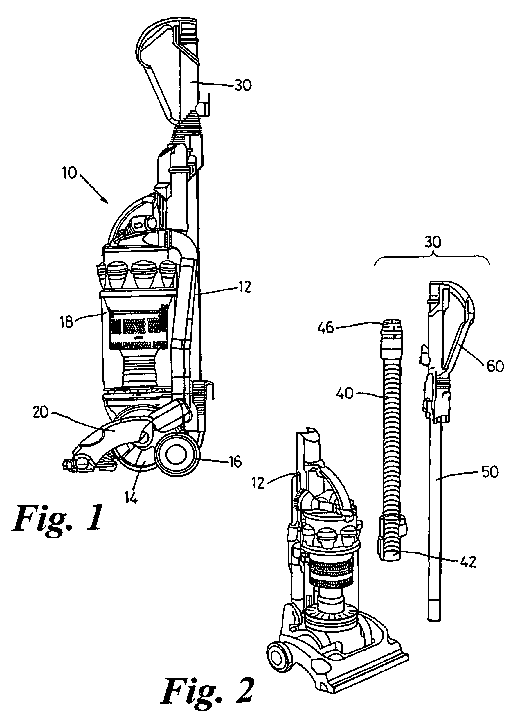
[0018]A vacuum cleaner incorporating a handle assembly according to the invention is shown in FIG. 1. The upright vacuum cleaner 10 shown in FIG. 1 has a main body 12 which includes a motor casing 14, supporting wheels 16 and dirt- and dust-separating apparatus 18. The vacuum cleaner 10 also has a cleaner head 20 and a handle assembly 30. In the embodiment shown, the dirt- and dust-separating apparatus 18 comprises a cyclonic arrangement but this could readily be replaced by a filter, a bag or a combination of different known separation devices. The nature of the dirt- and dust-separating apparatus 18 is not material to the present invention.

[0019]It will be understood that, in normal upright use, the vacuum cleaner 10 is manoeuvred over a surface to be cleaned (a floor surface) whilst the motor causes dirty air to be sucked into the cleaner 10 via the cleaner head 20. The dirty air is passed to the dirt- and dust-separating apparatus 18 where the dirt and dust is extracted and clea...


PUM


Abstract

A handle assembly for a cleaning appliance includes a handle portion and a tubular wand having an open end configured to receive tools or other accessories when the cleaning appliance is in use. The handle assembly also includes a wand cap which is movable between a first position in which the wand cap covers the open end of the tubular wand and a second position in which the open end of the tubular wand is not covered by the wand cap. The wand cap is releasably connected to the handle portion or the tubular wand in a snap-fit manner. This provides an advantageous construction which reduces the risk of damage and the cost of repair.

Description

REFERENCE TO RELATED APPLICATIONS[0001]This application is a national stage application under 35 USC 371 of International Application No. PCT / GB2005 / 002604, filed Jul. 1, 2005, which claims the priority of United Kingdom Application No. 0416359.8, filed Jul. 22, 2004, the contents of both of which prior applications are incorporated herein by reference.FIELD OF THE INVENTION[0002]The invention relates to a handle assembly for a cleaning appliance, particularly but not exclusively to a handle assembly for a vacuum cleaner of the upright type.BACKGROUND OF THE INVENTION[0003]The general construction and method of operation of upright vacuum cleaners are both well known. Also well known is the capability of upright vacuum cleaners to be converted from a traditional upright cleaning mode (in which the entire vacuum cleaner is manoeuvred across a floor surface) into a cylinder mode for “above-the-floor” cleaning. For such purposes, upright cleaners often incorporate an integral hose and ...

Claims


Application Information

Patent Timeline
Patent Type & Authority Patents(United States)
IPC IPC(8): A47L9/00A47L5/32A47L9/24A47L9/32
CPCA47L5/32A47L9/244A47L9/325
Inventor LIDDELL, SARAH HELEN
Owner DYSON TECH LTD
Why Eureka
Try Eureka