
Battery control apparatus, electric vehicle, and computer-readable medium storing a program that causes a computer to execute processing for estimating a state of charge of a secondary battery

a control apparatus and secondary battery technology, applied in battery/fuel cell control arrangement, secondary cell servicing/maintenance, instruments, etc., can solve the problems of inaccurate estimation of soc based on cumulative charge/discharge current value of secondary battery, and inability to accurately estimate soc if. , to achieve the effect of accurate estimation of a state of charge and short period of tim

Inactive Publication Date: 2011-02-22
PANASONIC EV ENERGY CO LTD
View PDF9 Cites 18 Cited by
  • Summary
  • Abstract
  • Description
  • Claims
  • Application Information

AI Technical Summary

Benefits of technology

The present invention relates to a battery control apparatus that can accurately estimate the state of charge of a secondary battery in a short period of time after a charge / discharge operation. The apparatus determines if the battery generates a polarization voltage in response to a stop-of-power supply and uses this information to estimate the initial state of charge. The apparatus sets an initial value based on the previous state of charge and uses the peak battery voltage drop and peak discharge current to estimate the present state of charge. The apparatus can also consider the effect of polarization voltage and adjust the initial value accordingly. The technical effect of this invention is to provide a more accurate and efficient way to estimate the state of charge of a secondary battery.

Problems solved by technology

However, immediately after starting a charge / discharge operation of a secondary battery, an estimated SOC based on a cumulative charge / discharge current value of the secondary battery is inaccurate because only a short period of time is available for measuring the charge / discharge current.
Therefore, the SOC estimating method discussed in Japanese Laid-Open Patent Application No. 2005-300418 may not accurately estimate the SOC if a polarization voltage is generated.

Method used


Image

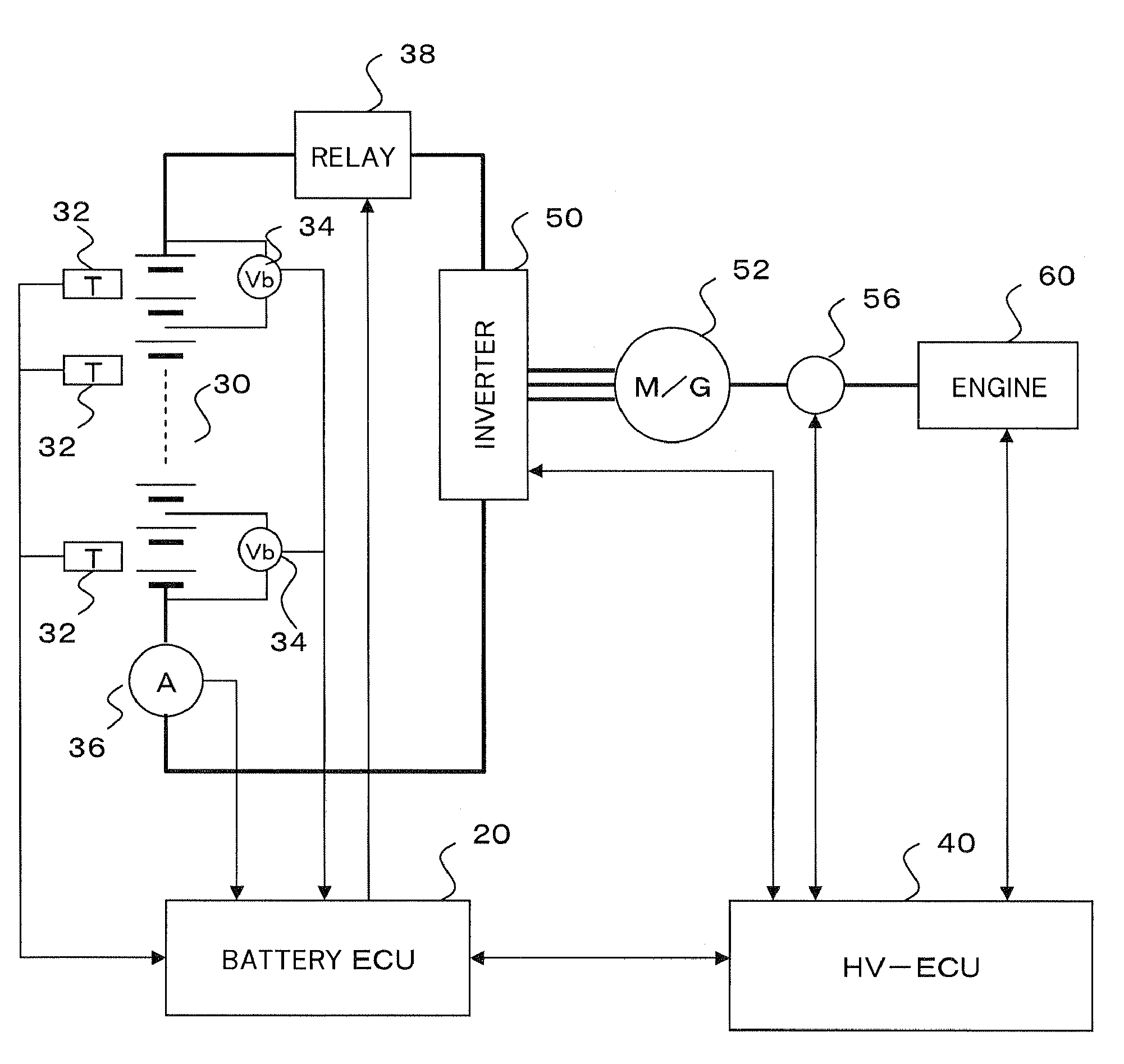
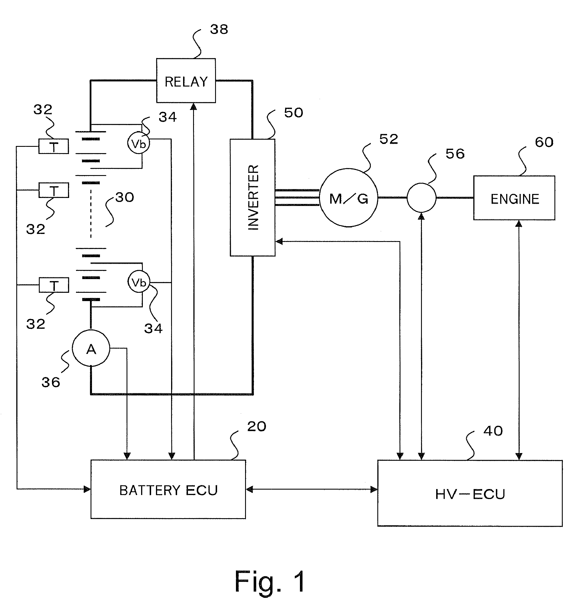
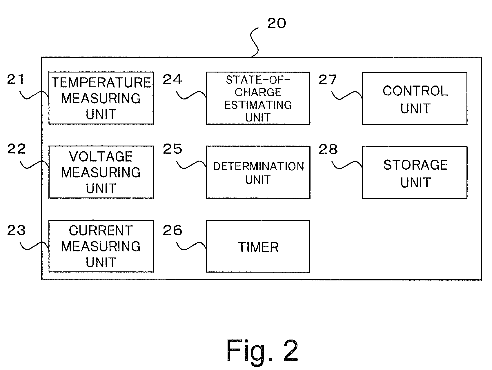
  • Battery control apparatus, electric vehicle, and computer-readable medium storing a program that causes a computer to execute processing for estimating a state of charge of a secondary battery
  • Battery control apparatus, electric vehicle, and computer-readable medium storing a program that causes a computer to execute processing for estimating a state of charge of a secondary battery
  • Battery control apparatus, electric vehicle, and computer-readable medium storing a program that causes a computer to execute processing for estimating a state of charge of a secondary battery

Examples


first modified embodiment

[0073]The following is the present embodiment.

[0074]FIG. 6 is a flowchart illustrating a processing procedure for the battery ECU 20 and the HV-ECU 40 in an engine startup operation according to the first modified embodiment.

[0075]As illustrated in FIG. 6, according to the first modified embodiment, if the engine startup operation has failed (NO in step S124), the processing flow proceeds to step S130. In step 130, the battery ECU 20 determines whether the charge / discharge dormant period of the secondary battery 30 is shorter than the predetermined time ta. If the charge / discharge dormant period is shorter than the predetermined time ta (YES in step S130), the battery ECU 20 prohibits the motor generator 52 from operating. If the dormant period is equal to or longer than the predetermined time ta (NO in step S130), the processing flow proceeds to step S132. In step S132, the battery ECU 20 activates the motor generator 52 again.

[0076]As described above, if an engine startup operatio...

second modified embodiment

[0077]The following is the present embodiment.

[0078]The above-described embodiments may inaccurately estimate the SOC if there are any measurement errors in the detection of the discharge current and the battery voltage, even if a polarization voltage of the secondary battery 30 is taken into consideration in the estimation of the present SOC.

[0079]In view of the foregoing, the second modified embodiment is configured to evaluate the present SOC when the present SOC is obtained.

[0080]FIG. 7 is a flowchart illustrating a processing procedure for the battery ECU 20 and the HV-ECU 40 in an engine startup operation according to a second modified embodiment.

[0081]As illustrated in FIG. 7, the second modified embodiment includes step S118 of obtaining a present SOC based on the battery temperature T, the peak discharge current Is, and the peak battery voltage drop ΔVs. Then, in step S119, the battery ECU 20 determines whether the present SOC is higher than the previous SOC. If the present...

third modified embodiment

[0083]The following is the present embodiment.

[0084]If the secondary battery 30 is left for a long time, the secondary battery 30 causes a self discharge and an SOC may be significantly lower than the previous SOC when a charge / discharge of the secondary battery 30 resumes. In such a case, an overdischarge phenomenon may appear immediately after the charge / discharge operation of the secondary battery 30 resumes. Hence, the third modified embodiment executes predetermined anti-overdischarge processing (which may be referred to as “low-voltage cut-off” processing) when the charge / discharge operation of the secondary battery 30 resumes, i.e., when the present SOC estimated in the engine startup operation falls below a predetermined SOC level (i.e., a criteria being set for determining the possibility of causing an overdischarge in the secondary battery 30).

[0085]FIG. 8 is a flowchart illustrating a processing procedure for the battery ECU 20 and the HV-ECU 40 in an engine startup opera...


PUM

PropertyMeasurementUnit
timeaaaaaaaaaa
temperatureaaaaaaaaaa

Abstract

The present invention can speedily and accurately estimate an SOC of a secondary battery immediately after a charge / discharge operation resumes. A determination unit determines whether a dormant period is longer than a predetermined time in response to an initiation of power supply from a secondary battery to a motor generator. The dormant period is equivalent to the duration from a previous stop of power supply to a present initiation of power supply. If the dormant period is longer than the predetermined time, a state-of-charge estimating unit sets an initial SOC based on a peak battery voltage drop ΔVs and a peak discharge current Is, wherein the peak battery voltage drop ΔVs represents a difference between a battery voltage Vo measured before initiating power supply and a lowest battery voltage Vs measured after initiating power supply and the peak discharge current Is represents a maximum current value measured after initiating power supply. The state-of-charge estimating unit estimates a state of charge of the secondary battery 30 based on the initial SOC as a value effective immediately after initiating power supply.

Description

PRIORITY INFORMATION[0001]This application claims priority to Japanese Patent Application No. 2006-240333 filed on Sep. 5, 2006, which is incorporated herein by reference in its entirety.BACKGROUND OF THE INVENTION[0002]1. Field of the Invention[0003]The present invention relates to a battery control apparatus configured to estimate a state of charge of a secondary battery.[0004]2. Description of the Related Art[0005]A conventional technique enables estimating a state of charge (hereinafter, referred to as SOC) of a secondary battery, such as a nickel-metal hydride battery or a lithium-ion battery, and controlling a charge / discharge operation of the secondary battery based on an estimated SOC.[0006]For example, a method discussed in Japanese Laid-Open Patent Application No. 11-174134 estimates an SOC based on a cumulatively measured charge / discharge current value of a secondary battery during a predetermined period of time.[0007]However, immediately after starting a charge / discharge...

Claims


Application Information

Patent Timeline
Patent Type & Authority Patents(United States)
IPC IPC(8): H02J7/00H01M10/46H02J7/14H01M10/44B60L3/00B60R16/04G01R31/36H01M10/48
CPCB60L11/1861H02J7/0016Y02T10/7055Y02T10/7044Y02T10/705Y02T10/7011B60L58/12Y02T10/70
Inventor SUZUKI, MASAHIKOTOGASHI, KOUTAUEMURA, YUKIEKANAMARU, KUNIO
Owner PANASONIC EV ENERGY CO LTD
Learn More