Three-dimensional finite element modeling of human ear for sound transmission

a technology of finite element modeling and human ear, which is applied in the field of three-dimensional finite element modeling of human ear for sound transmission, can solve the problems of difficult system understanding and simulation of the function of the ear, and it is not always possible to model the realistic acoustic-mechanical response in the ear involving complex geometry and an array of material compositions, so as to facilitate fabrication or rapid prototyping, and provide information.

Inactive Publication Date: 2011-02-22
THE BOARD OF RGT UNIV OF OKLAHOMA
View PDF3 Cites 5 Cited by
  • Summary
  • Abstract
  • Description
  • Claims
  • Application Information

AI Technical Summary

Benefits of technology

[0013]The accurate and comprehensive FE model of the present invention has sufficient functional feasibility for analyzing and predicting the dynamics of the human ear under normal and pathological conditions, as well as reconstructed and implanted conditions. As such, the FE model of the present invention can be applied to a broad number of applications, such as (1) diagnosis of conditions of the ear, (2) design of implantable hearing devices, (3) evaluation of implantable devices or surgical treatment and combinations thereof. Thus, it can improve the basic understanding of the hearing mechanism and sound transmission of the ear. It can also be used to assess the influence of ear diseases on hearing by simulating structural or environmental alterations of the ear caused by diseases. Further, it can facilitate the diagnosis and the treatment of hearing loss. For example, the computational FE model of the present invention can be incorporated into clinical tools to improve diagnostic effectiveness for ear diseases, such as otitis media, TM perforation, otoscelerosis, or ossicular disarticulations and fixation. Also, surgical approaches or treatments performed to restore hearing can be computationally evaluated. Furthermore, the FE model of the present invention can be used to research and evaluate the design and performance of middle ear implants and implantable hearing devices. For example, it can be used to determine the effects of implanted actuators or transducers on the middle ear ossicular and cochlear functions. It can also be used to evaluate electromagnetic-mechanical coupling of devices which correlate electromagnetic fields into mechanical ear vibration.
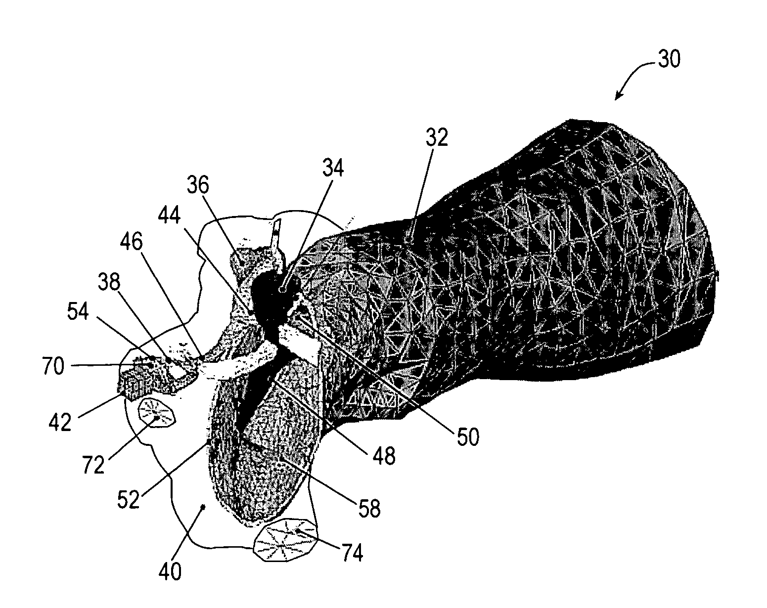
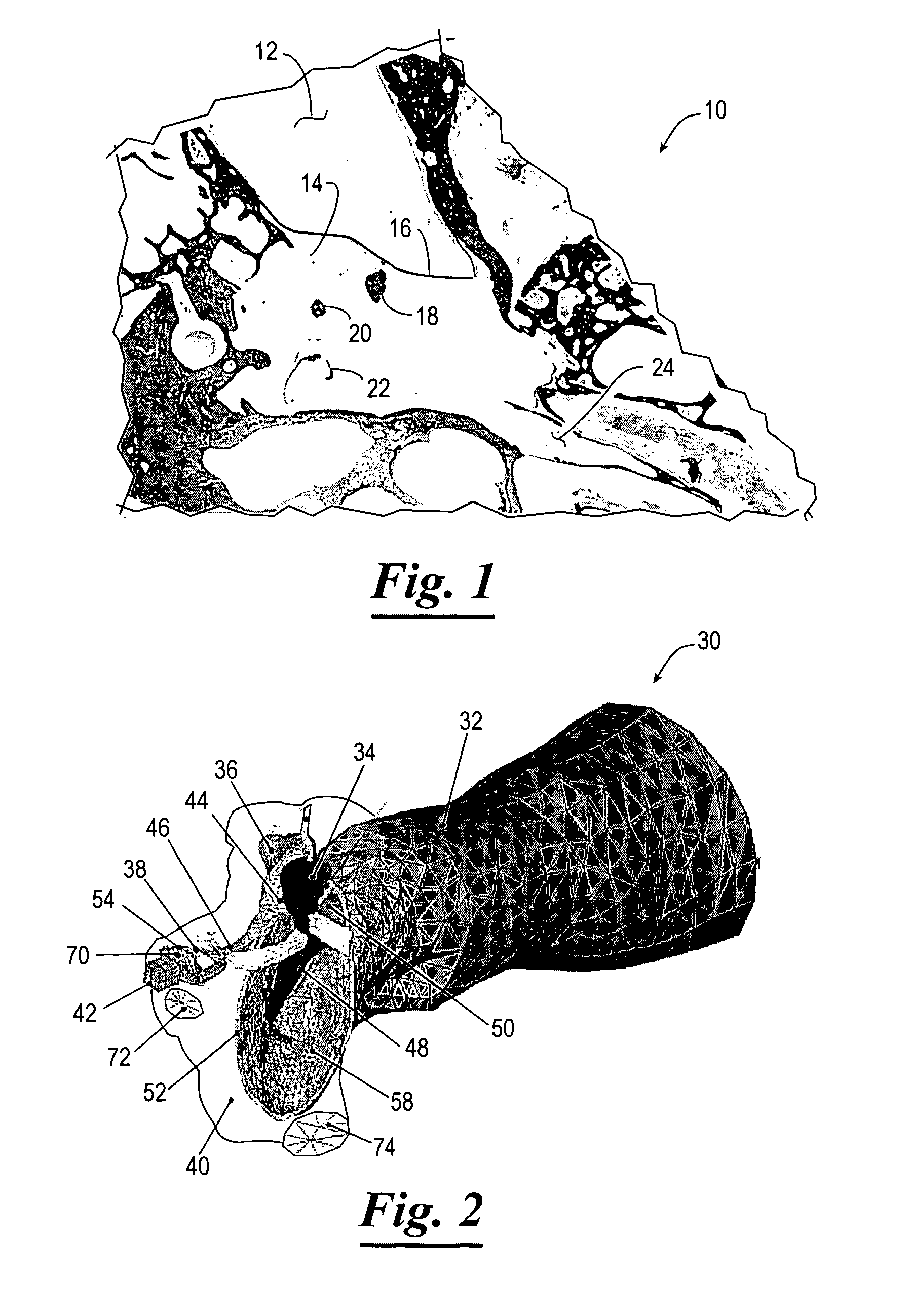
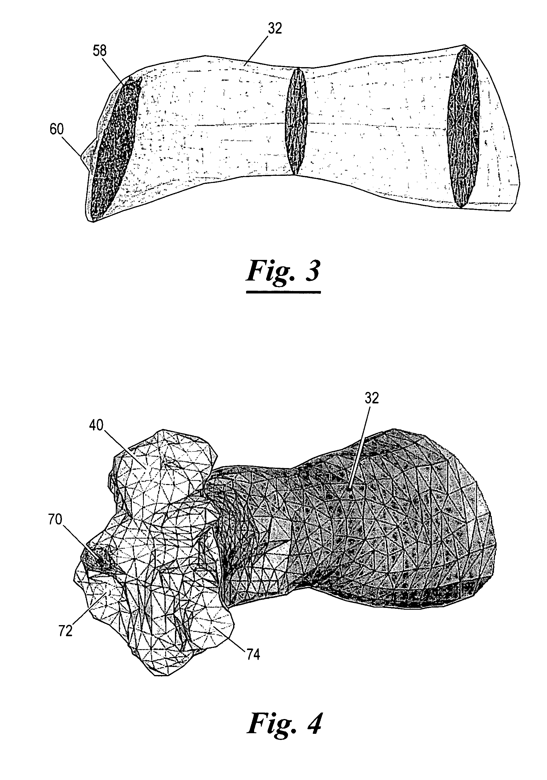
[0023]While other ear models exist, the computational FE model of the present invention has the following unique features: 1) it models accurate anatomical structures of the entire ear including normal, diseased and implanted ears, 2) it can readily provide information to facilitate the fabrication or rapid prototyping of a visual, physical model of the ear, 3) it allows for acoustic-mechanical (i.e., air-structure-fluid) coupled analysis on sound transmission through the ear, and 4) it allows for electromagnetic-mechanical or piezoelectric-mechanical coupled analysis of implantable hearing devices in the ear.

Problems solved by technology

While the analytical approach worked reasonably well for some limited situations, it was not always possible to model the realistic acoustic-mechanical response in the ear involving complex geometry and an array of material compositions.
FE models can also determine the detailed vibration shapes, stress distributions, and dynamic behaviors at any locations in a system, which is not possible with analytical solutions.
However, the ear is a complex system formed of air, liquid and mechanical structures making the function of the ear a very difficult system to understand and simulate.

Method used


Image

  • Three-dimensional finite element modeling of human ear for sound transmission
  • Three-dimensional finite element modeling of human ear for sound transmission
  • Three-dimensional finite element modeling of human ear for sound transmission

Examples


Embodiment Construction

[0049]Presently preferred embodiments of the invention are shown in the above-identified figures and described in detail below. In describing the preferred embodiments, like or identical reference numerals are used to identify common or similar elements. The figures are not necessarily to scale and certain features and certain views of the figures may be shown exaggerated in scale or in schematic in the interest of clarity and conciseness.

[0050]Illustrative embodiments of the invention are described below. In the interest of clarity, not all features of an actual implementation are described in this specification. It will of course be appreciated that in the development of any such actual embodiment, numerous implementation-specific decisions must be made to achieve the developers' specific goals, such as compliance with system-related and business-related constraints, which will vary from one implementation to another. Moreover, it will be appreciated that such a development effort...


PUM


Abstract

A finite element model of an ear stored on a computer readable medium having logic representing a three-dimensional geometric model of the ear; logic for meshing individual anatomical structures of the ear accounting for whether the anatomical structures include at least one of air, liquid material and solid material; logic for assigning material properties for each anatomical structure based on at least one physical property of each anatomical structure; logic for assigning boundary conditions for some of the anatomical structures indicative of interaction between such anatomical structures; and logic for employing acoustic-structural coupled analysis to the anatomical structures of the ear to generate data indicative of the acoustic effect on mechanical vibration transmission in the ear.Various embodiments of “one-chamber” and “two-chamber” analyses and models are described.

Description

CROSS-REFERENCE TO RELATED APPLICATIONS[0001]The present patent application claims priority to the provisional patent application identified by U.S. Ser. No. 60 / 685,026 filed on May 26, 2005, the entire content of which is hereby incorporated herein by reference.STATEMENT REGARDING FEDERALLY SPONSORED RESEARCH OR DEVELOPMENT[0002]Not Applicable.THE NAMES OF THE PARTIES TO A JOINT RESEARCH AGREEMENT[0003]Not Applicable.REFERENCE TO A “SEQUENCE LISTING,” A TABLE, OR A COMPUTER PROGRAM LISTING APPENDIX SUBMITTED ON A COMPACT DISC AND AN INCORPORATION-BY-REFERENCE OF THE MATERIAL ON THE COMPACT DISC[0004]Not Applicable.BACKGROUND OF THE INVENTION[0005]The ear transfers sound through the external ear canal and middle ear into the inner ear (cochlea). The external ear canal collects sound pressure waves and transfers them to the tympanic membrane. The middle ear, which includes tympanic membrane (or eardrum) and three ossicular bones (i.e., malleus, incus and stapes) suspended in an air-f...

Claims


Application Information

Patent Timeline
Patent Type & Authority Patents(United States)
IPC IPC(8): G06T15/00
CPCA61B5/12A61B5/4504A61B5/4523B33Y80/00A61B5/4533A61B34/10A61B5/4528
Inventor GAN, RONG Z.
Owner THE BOARD OF RGT UNIV OF OKLAHOMA
Why Eureka
Try Eureka