Image capturing apparatus, method of controlling the same, and program

a technology of image capturing apparatus and control method, which is applied in the direction of optical radiation measurement, color signal processing circuit, instruments, etc., can solve the problems of user inability to confirm the position and size of dust particles before or during shooting, and the generation of dust such as metal powder in the camera body

Inactive Publication Date: 2011-02-22
CANON KK
View PDF8 Cites 9 Cited by
  • Summary
  • Abstract
  • Description
  • Claims
  • Application Information

AI Technical Summary

Benefits of technology

[0009]The present invention has been made in consideration of the above-described problem, and has as its object to easily notify, before shooting, a user of the degree of foreign substance sticking to, e.g., an optical filter arranged in front of an image sensor.

Problems solved by technology

When these mechanical units operate, dust such as metal powder may be generated in the camera body.
When a foreign substance such as dust sticks to the surface of an optical element (e.g., optical low-pass filter) arranged in front of an image sensor included in the image capturing unit of the digital camera, the image of the foreign substance is contained in a sensed image, resulting in degradation in the image quality.
However, the digital camera requires no operation of feeding the film frame in every shooting, and therefore, sensed images continuously contain the same foreign substance at the same position.
In the conventional method, however, the user cannot confirm the position and size of a dust particle before or during shooting.
For this reason, the user cannot predict the degree of influence of the dust image on a sensed main object.

Method used


Image

  • Image capturing apparatus, method of controlling the same, and program
  • Image capturing apparatus, method of controlling the same, and program
  • Image capturing apparatus, method of controlling the same, and program

Examples


first embodiment

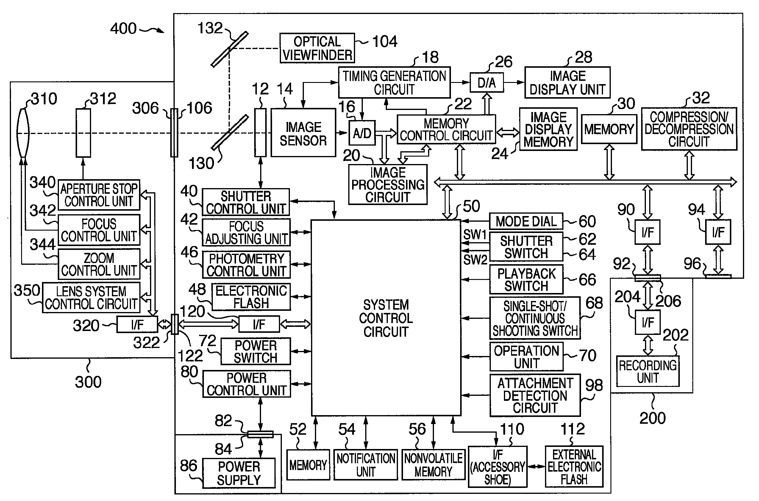
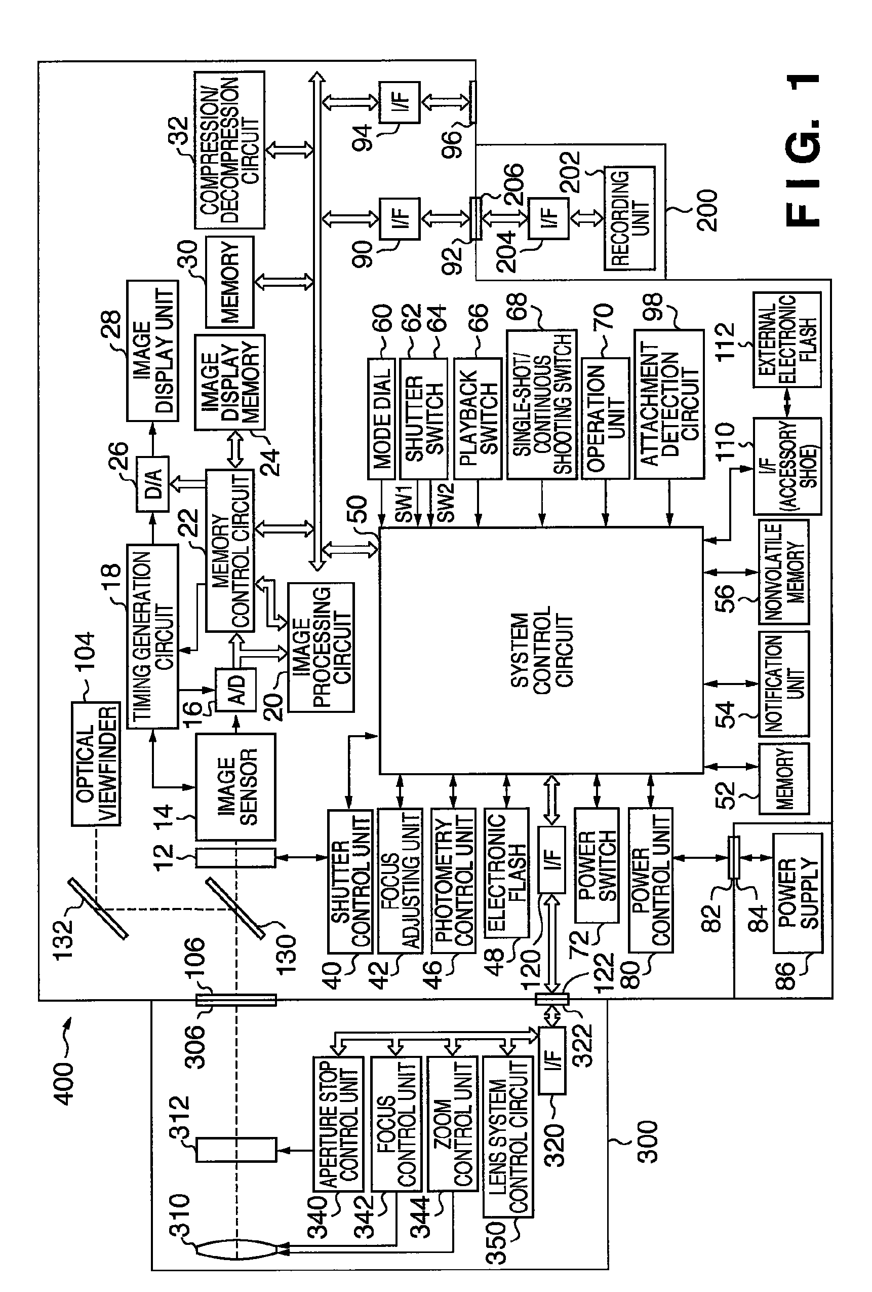
[0031]FIG. 1 is a block diagram showing the arrangement of an image capturing apparatus having an image processing function according to the first embodiment of the present invention. In this embodiment, a lens-interchangeable single-lens reflex digital still camera will be exemplified as the image capturing apparatus. The present invention is applicable not only to the single-lens reflex digital still camera but also to, e.g., a lens-interchangeable digital video camera.

[0032]Referring to FIG. 1, a single-lens reflex digital still camera 400 mainly includes a camera body 100 and a lens unit 300 of interchangeable-lens type.

[0033]The lens unit 300 includes an imaging lens 310 formed from a plurality of lenses, an aperture stop 312, and a lens mount 306 which mechanically connects the lens unit 300 to the camera body 100. The lens mount 306 incorporates various mechanisms for electrically connecting the lens unit 300 to the camera body 100. An interface 320 connects the lens unit 300...

second embodiment

[0113]In the first embodiment, the window is divided into blocks, and processing is executed in each block. In the second embodiment, a method of notifying a user of a dust position using a focus measuring point selection frame of live view will be described. A digital camera according to the second embodiment has the same arrangement as in the first embodiment, and a description thereof will not be repeated. Only operations different from the first embodiment will be described.

[0114]FIG. 12 is a view showing an example of a live view display window. The rectangle in the display window is a focus measuring frame for designating a desired focus point. The user can freely move (select the position of) the focus measuring frame in the window by operating a focus measuring frame moving button included in an operation unit 70.

[0115]As in the first embodiment, assume that it is determined based on dust information stored in a nonvolatile memory 56 that dust particles are present at positi...

third embodiment

[0120]In this embodiment, a method of notifying a user of the presence / absence of dust by automatically enlarging the dust position at the start of live view using dust information will be described. A digital camera according to the third embodiment has the same arrangement as in the first embodiment, and a description thereof will not be repeated. Only operations different from the first embodiment will be described. In this embodiment, dust information represents that dust particles stick at positions indicated by circles in FIG. 15.

[0121]As described above, generally, image data output from an image sensor 14 is reduced and displayed in live-view, as shown in FIG. 9. Hence, a dust particle which sticks to an optical element arranged in front of the image sensor 14 and actually forms an image disappears from the image data upon reduction processing and cannot be confirmed in live view display.

[0122]To prevent this, when the user starts live view, each dust position is obtained fr...


PUM

PropertyMeasurementUnit
sizeaaaaaaaaaa
coloraaaaaaaaaa
densityaaaaaaaaaa

Abstract

An image capturing apparatus includes an image capturing unit which causes an image sensor to photoelectrically convert an object image to generate an image signal, a display unit which displays the image signal generated by the image capturing unit, a storage unit which stores foreign substance information that is information about at least the position and size of a foreign substance sticking to the surface of an optical element arranged in front of the image sensor, and a control unit which controls the display unit to display the image signal while superimposing, on it, an image which represents presence of the foreign substance and is generated based on the foreign substance information stored in the storage unit during a live view operation of sequentially displaying, on the display unit, image signals sequentially generated by the image capturing unit.

Description

BACKGROUND OF THE INVENTION[0001]1. Field of the Invention[0002]The present invention relates to a technique of notifying a user of degradation in image quality caused by a foreign substance sticking to the surface of, e.g., an optical low-pass filter arranged in front of an image sensor in an image capturing apparatus which uses an image sensor such as a CCD or CMOS sensor.[0003]2. Description of the Related Art[0004]When the lens is detached from the camera body of a lens-interchangeable digital camera, dust particles floating in air may enter the camera body. The camera incorporates various mechanical units such as a shutter mechanism which mechanically operate. When these mechanical units operate, dust such as metal powder may be generated in the camera body.[0005]When a foreign substance such as dust sticks to the surface of an optical element (e.g., optical low-pass filter) arranged in front of an image sensor included in the image capturing unit of the digital camera, the ima...

Claims


Application Information

Patent Timeline
Patent Type & Authority Patents(United States)
IPC IPC(8): H04N5/222H04N5/76G01N21/88G02B7/36G03B7/28G03B13/36G03B17/18H04N5/225H04N5/232H04N101/00
CPCG03B13/18H04N5/2171H04N5/23241H04N5/23209H04N23/811H04N23/663H04N23/67H04N23/65H04N23/635
Inventor IKEDA, YASUYUKI
Owner CANON KK
Why Eureka
Try Eureka