Method and apparatus for the high spatial resolution imaging of a structure marked with a substance

a high spatial resolution and imaging technology, applied in the field of high spatial resolution imaging of structures, can solve the problems of fluorescent dyes, undesirable chemical conversion of fluorescent dyes, and methods appertaining to fluorescence microscopy

Active Publication Date: 2011-02-22
MAX PLANCK GESELLSCHAFT ZUR FOERDERUNG DER WISSENSCHAFTEN EV
View PDF10 Cites 3 Cited by
  • Summary
  • Abstract
  • Description
  • Claims
  • Application Information

AI Technical Summary

Benefits of technology

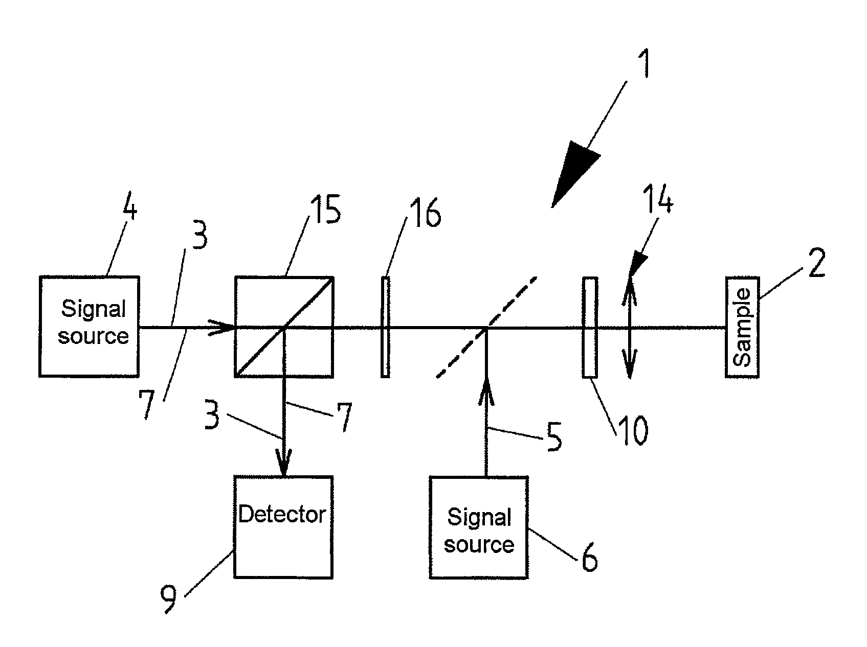
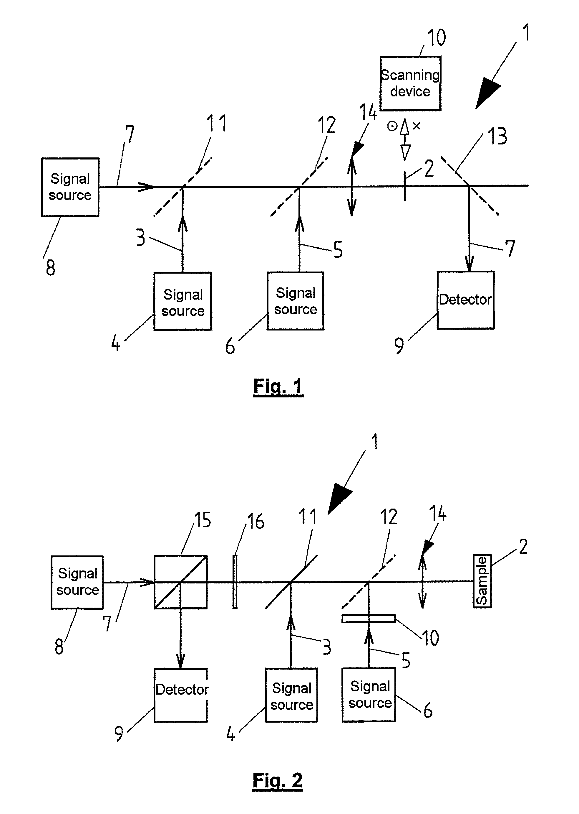
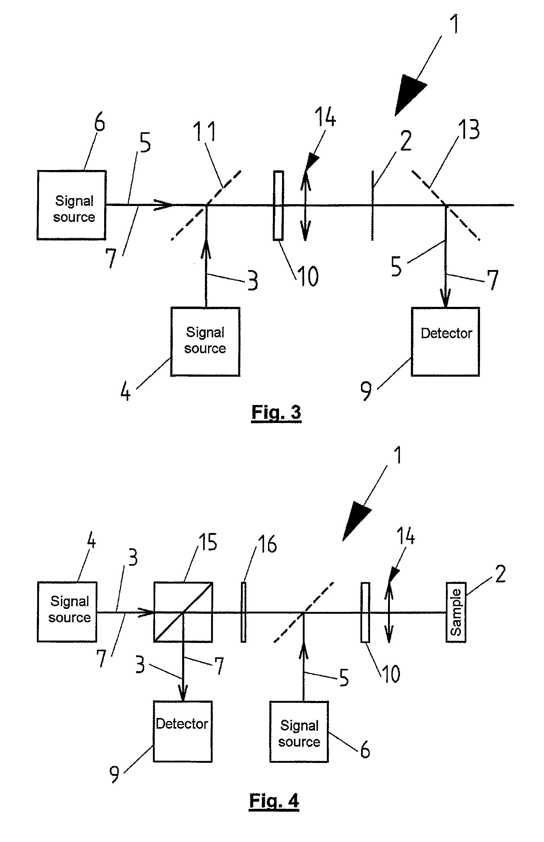
[0023]The refractive index change in the sample which is associated with the temperature increase and which can be detected by the phase shift of a signal passing through the sample, or alternatively by scattered light, all the better, the greater it is, depends not only on the absorption cross section for the second electromagnetic signal and hence the absolute temperature change but also on the specific refractive index change in the sample with temperature. Therefore, it is advantageous to embed the sample to be examined into a medium in which the temperature increase is associated with a particularly high refractive index change. Thus, many organic liquid media have a refractive index reduction of 0.0005 per 1 K temperature increase, whereas water has only a refractive index reduction of 0.0001 per 1° C. As an alternative or in addition, the sample can be set to such a temperature at which the temperature increase brought about by the second electromagnetic signal, in the medium present, brings about a refractive index jump that is as large as possible. Thus, in the case of aqueous samples it is advantageous to cool the sample, wherein a sample temperature of −10 to 5° C. is particularly favorable with regard to a large refractive index change in the event of a temperature change.
[0029]Particularly preferably, the second electromagnetic signal is applied to the sample in pulses having a high intensity density, wherein the temporary local temperature increase in the sample is detected directly after each pulse of the second electromagnetic signal. In this way it is possible to temporarily form in the sample a very high temperature gradient on account of the local temperature increase in the sample. Correspondingly, the effect is particularly large with regard to the phase shift of the electromagnetic signal used for detecting the local temperature increase. At the same time, however, on average only little thermal energy is input into the sample by the pulsed second electromagnetic signal, with the result that it is also possible to observe living biological samples without thermally destroying the latter.

Problems solved by technology

Methods appertaining to fluorescence microscopy have the known fundamental disadvantage of the bleaching of the fluorescent dyes used.
This means that a fluorescent dye can only undergo a finite number of excitation and fluorescence emission cycles, usually fewer than 100 000, before it incurs an undesirable chemical conversion into a state that is permanently no longer fluorescent.
This problem also occurs in the case of the RESOLFT and SPARSE techniques described above.
An additional factor is that the first electromagnetic signal used to set the spatial distribution of the portion of the substance in the fluorescent state can likewise lead to a burdening and thus possibly earlier bleaching of the substance.
In addition, besides the absolute yield of fluorescent light from a molecule of a fluorescent dye, the quantity of fluorescent light that is obtainable therefrom during a specific period of time is also limited.
Long measurement times are not just uneconomic in principle, but regularly pose problems with drifting of various components of the measurement setup used.

Method used


Image

  • Method and apparatus for the high spatial resolution imaging of a structure marked with a substance
  • Method and apparatus for the high spatial resolution imaging of a structure marked with a substance
  • Method and apparatus for the high spatial resolution imaging of a structure marked with a substance

Examples


Embodiment Construction

[0041]S. Berciaud et al.: “Photothermal heterodyne imaging of individual metallic nanoparticles: Theory versus experiment” in PHYSICAL REVIEW B 73, 045424 (2006) have reported that gold nanoparticles having a size of 1.4 nm (67 atoms) can be detected by the PHI technique. The absorption cross section of photochromic dyes at the wavelength maximally absorbed by them is of the same order of magnitude as that of gold atoms in a cluster. Accordingly, at least those regions of a structure marked with a photochromic dye which have a few 10 molecules of the photochromic dye in the first state can be photothermally imaged in accordance with the novel method. At a sufficiently high concentration of the photochromic dye, this condition is noncritical even when the photochromic dye in the sample is changed over by means of the first electromagnetic signal from the first state into the second state with the smaller absorption cross section apart from a region, in each case, which has smaller di...


PUM

PropertyMeasurementUnit
sizeaaaaaaaaaa
temperatureaaaaaaaaaa
refractive indexaaaaaaaaaa

Abstract

For the high spatial resolution imaging of a structure in a sample (2) the structure is marked with a substance which can be changed over by means of a first electromagnetic signal (5) from a first state having a larger absorption cross section for a second electromagnetic signal (3) into a second state having a smaller absorption cross section for the second signal (3) or which can be changed over by means of a first electromagnetic signal (5) into a first state having a larger absorption cross section for a second electromagnetic signal (3) from a second state having a smaller absorption cross section for the second signal (3). A spatially delimited distribution of a portion of the substance in the first state is then set by means of the first signal (5). Afterward, the second electromagnetic signal (3) is applied to the sample (2), and a local temperature increase in the sample (2) which results from the larger absorption cross section of the substance in the first state is detected.

Description

CROSS-REFERENCE TO RELATED APPLICATIONS[0001]This application is a continuation of the international patent application PCT / EP2007 / 010905 entitled “Spatial high Resolution of a Structure”, filed on Dec. 12, 2007 and claiming the priority of German patent application No. DE 10 2006 060180.7, which is entitled “Verfahren und Vorrichtung zum räumlich hochaufgelösten Abbilden einer mit einer Substanz markierten Struktur” [“Method and apparatus for the high spatial resolution imaging of a structure marked with a substance”], was filed on Dec. 18, 2006 and is pending in parallel.FIELD OF THE INVENTION[0002]The invention relates to a method and an apparatus for the high spatial resolution imaging of a structure in a sample. In particular, the invention relates to a method and an apparatus for the high spatial resolution imaging of a structure in a sample wherein the structure is marked with a substance selected from a group of substances which can be changed over by means of a first electr...

Claims


Application Information

Patent Timeline
Patent Type & Authority Patents(United States)
IPC IPC(8): G01N21/25
CPCG01N21/64
Inventor HELL, STEFAN
Owner MAX PLANCK GESELLSCHAFT ZUR FOERDERUNG DER WISSENSCHAFTEN EV
Why Eureka
Try Eureka