
Flexible lithium niobate film electroencephalogram detection chip and device thereof

A detection device and detection chip technology, applied in the field of biological sensing, can solve the problems of inflexibility, increase the probability of electromagnetic interference, and difficult to fit, and achieve the effect of not easy electromagnetic interference.

Pending Publication Date: 2021-08-17
派尼尔科技(天津)有限公司
View PDF6 Cites 1 Cited by
  • Summary
  • Abstract
  • Description
  • Claims
  • Application Information

AI Technical Summary

Problems solved by technology

[0004] However, the research on the use of LiNbO3 modulators as biosensors is still relatively insufficient, and the problems it faces are: (1) the existing LiNbO3 3 Devices made of bulk materials are bulky, inflexible, and not easy to fit with the human body; (2) due to the traditional LiNbO 3 The device cannot be placed near the epidermis of the human brain, so the electrodes and the device are separated and need to be connected with metal wires, which increases the chance of electromagnetic interference

Method used


Image

  • Flexible lithium niobate film electroencephalogram detection chip and device thereof
  • Flexible lithium niobate film electroencephalogram detection chip and device thereof
  • Flexible lithium niobate film electroencephalogram detection chip and device thereof

Examples


Embodiment 1

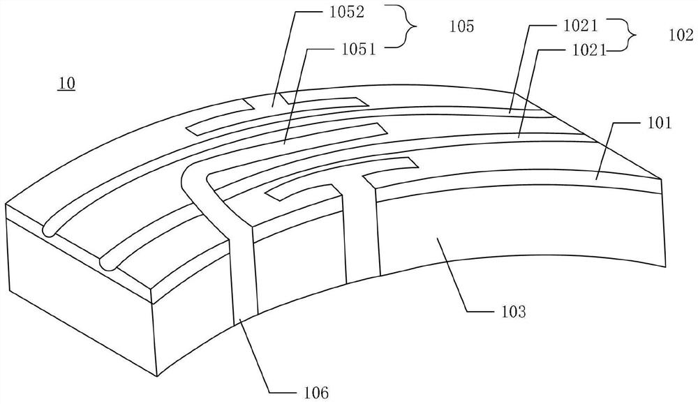
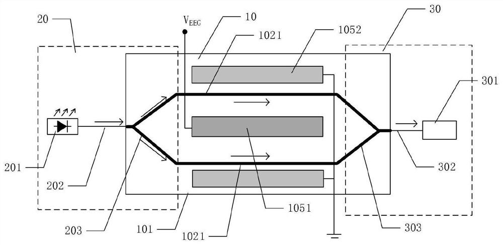
[0056] Such as figure 2 As shown, a flexible lithium niobate thin film EEG detection device is provided, including: a flexible lithium niobate thin film EEG detection chip 10, the chip includes: a flexible lithium niobate substrate 101, on which a light waveguide 102 and coplanar traveling wave electrode 105; and flexible support layer 103 ( figure 2 Not shown in ), used to provide support for the flexible lithium niobate substrate 101; the surface of the flexible support layer 103 is provided with electrodes 106 ( figure 2 not shown in ), the coplanar traveling wave electrode 105 is connected to the electrode 106.

[0057] The optical waveguide 102 includes a set of waveguide interference arms 1021 , the center electrode 1051 of the coplanar traveling wave electrode 105 is located between each set of waveguide interference arms 1021 , and the ground electrodes 1052 are located on both sides of each set of waveguide interference arms 1021 .

[0058] Optical input assembly...

Embodiment 2

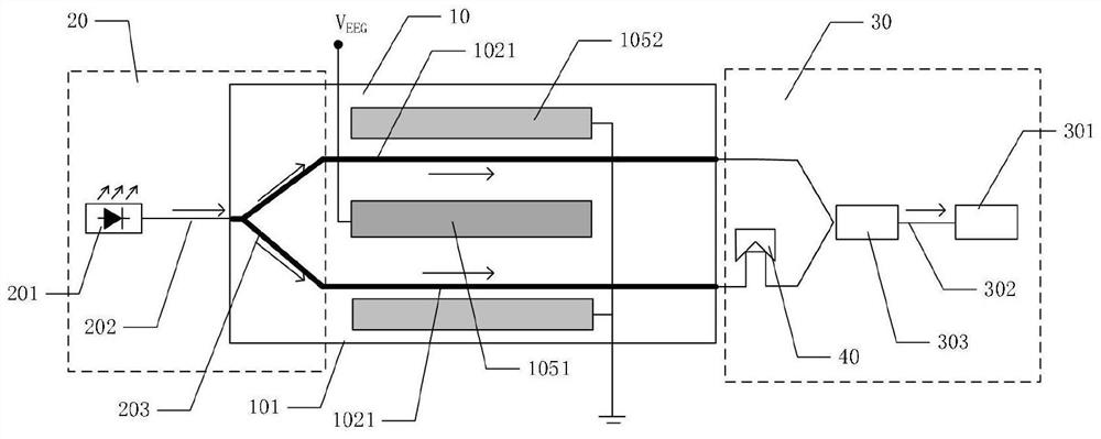
[0062] Such as figure 2 As shown, a flexible lithium niobate thin film EEG detection device is provided. The difference between this embodiment and embodiment 1 is that the optical fiber bundle structure 303 of this embodiment is an optical fiber bundle that is separately arranged with the flexible lithium niobate substrate. A phase delay device 40 is connected to one of the output optical fibers 302; the light wave emitted by the light source 201 is transmitted to the flexible lithium niobate Y waveguide by the input optical fiber 201, and the light wave is divided into two beams, and the EEG signal is transmitted to the coplanar traveling wave On the electrode, the light is transmitted from the waveguide through the modulation area where the refractive index changes, the optical path changes, and the phase changes at the same time, and is output through the output optical fiber 302, one of the light waves passes through the delay device 40, and finally the two output light w...

Embodiment 3

[0067] Such as Figure 4 As shown, a flexible lithium niobate thin-film EEG detection device is provided. The difference between this embodiment and embodiment 1 is that the optical fiber beam splitting structure 203 of this embodiment is an optical fiber beam splitter set separately from the flexible lithium niobate substrate. A phase delayer 40 is connected to one of the input optical fibers 202; the light wave emitted by the light source 201 is divided into two beams through the beam splitter, and one beam of light passes through the delayer 40 and is transmitted to the waveguide on the flexible lithium niobate substrate In the interference arm 1021, the EEG signal is transmitted to the coplanar traveling wave electrode 105, the optical path changes due to the change of the refractive index, and then the phase changes, and the light waves are combined by the Y waveguide and output by the output optical fiber 302, and the signal is transmitted to the remote end On the detect...


PUM


Abstract

The invention provides a flexible lithium niobate film electroencephalogram detection chip and a device thereof, and the chip comprises a flexible lithium niobate substrate which is provided with an optical waveguide and a coplanar traveling wave electrode; a flexible support layer used for providing support for the flexible lithium niobate substrate; and an electrode arranged on the surface of the flexible supporting layer, and wherein the coplanar traveling wave electrode is electrically connected with the electrode. According to the invention, the flexible lithium niobate substrate and the flexible supporting layer have flexibility and can be better attached to the surface of the human brain; the flexible supporting layer is attached to the surface of the human brain, the electrodes of the flexible supporting layer make electrical contact with the human brain, the electrodes collect electroencephalogram signals and transmit the electroencephalogram signals to the coplanar traveling wave electrodes on the lithium niobate substrate, a weak electric field is formed between the coplanar traveling wave electrodes, the refractive index of the flexible lithium niobate substrate is changed, light is transmitted from the optical waveguide and passes through the modulation area with the changed refractive index, the optical path is changed, and the phase is changed during output. and long-distance transmission is light transmission, so that the long-distance transmission is not easily interfered by electromagnetic interference.

Description

technical field [0001] The invention relates to the technical field of biosensing, in particular to a flexible lithium niobate thin-film EEG detection chip and a device. Background technique [0002] In recent years, brain science has become a hot spot in the current international frontier of science and technology, and countries around the world are competing to invest a lot of financial, material and human resources in the field of "brain science". At present, international brain science research is becoming more and more intense. The United States has entered the second stage of the brain project research. Although my country is at the international forefront in some technologies such as speech recognition and brain tissue imaging, there are more areas that need breakthroughs, such as brain detection. technical aspects. Therefore, the development of new brain detection technology research will help us to understand the precise understanding of brain nerve signals. [000...

Claims


Application Information

Patent Timeline
Patent Type & Authority Applications(China)
IPC IPC(8): A61B5/291A61B5/25A61B5/31
Inventor 华平壤丁宁
Owner 派尼尔科技(天津)有限公司
Learn More