Optical elements and methods of making optical elements

a technology of optical elements and optical elements, applied in the field of optical elements, can solve the problems of inability to achieve the desired combination of performance and cost, inconvenient manufacturing of optical elements, and inability to meet the requirements of many optical systems, and achieve the effect of high photoinduced refractive index changes and simplified manufacturing

Inactive Publication Date: 2009-03-05
CORNING INC
View PDF16 Cites 0 Cited by
  • Summary
  • Abstract
  • Description
  • Claims
  • Application Information

AI Technical Summary

Benefits of technology

[0011]The devices and methods of the present invention result in a number of advantages over prior art devices and methods. For example, the present invention provides a method suitable for the fabrication of bulk (i.e. not guided wave) Bragg grating devices. The method uses a photosensitive glass material that may be fabricated using conventional glass melting techniques, providing for simplified manufacture of a variety of shapes. The method may be performed using a conventional 248 nm laser exposure system. The optical elements of the present invention have high photoinduced refractive index changes that are stable at elevated temperatures.

Problems solved by technology

Many photosensitive materials have been used; however, few have provided the desired combination of performance and cost.
For example, Bragg gratings have been recorded in germanium-doped silica glass optical fibers; while such gratings are relatively robust, the fiber geometry and high melting point of the material make these gratings inappropriate for many optical systems.
These filters had narrow-band filtering performance, but suffered from low thermal stability, opacity in the UV region, and sensitivity to visible radiation after recording.
Photosensitive polymers have also been used as substrates for Bragg gratings; however, devices formed from polymeric materials tend to have high optical losses and high temperature sensitivity.
These glasses had very high absorbances at wavelengths less than 300 nm, making them unsuitable for use with commonly used 248 nm excimer laser exposure systems.

Method used


Image

  • Optical elements and methods of making optical elements
  • Optical elements and methods of making optical elements
  • Optical elements and methods of making optical elements

Examples


example 1

[0034]The photosensitive glass materials of Table 2 were melted using methods familiar to the skilled artisan. Iota sand, boric acid, sodium chloride, sodium nitrate, sodium silicofluoride, antimony trioxide, zinc oxide and alumina were used as batch materials. The batched mixture was ball milled for 60 minutes, melted at 1425° C. for four hours, cast into slabs 4 inches wide and 1 inch thick, and annealed at 650° C. Concentrations are given in wt % on an as-batched basis.

TABLE 2A [265 EA]BCD [265 IC]SiO267.167.167.167.1B2O315.115.715.716.1Na2O8.98.38.37.3Al2O30003.0ZnO5.05.05.05.0F1.71.71.71.7Sb2O32.02.02.01.0Ag0.660.440.220.33Cl0.220.220.220.22

example 2

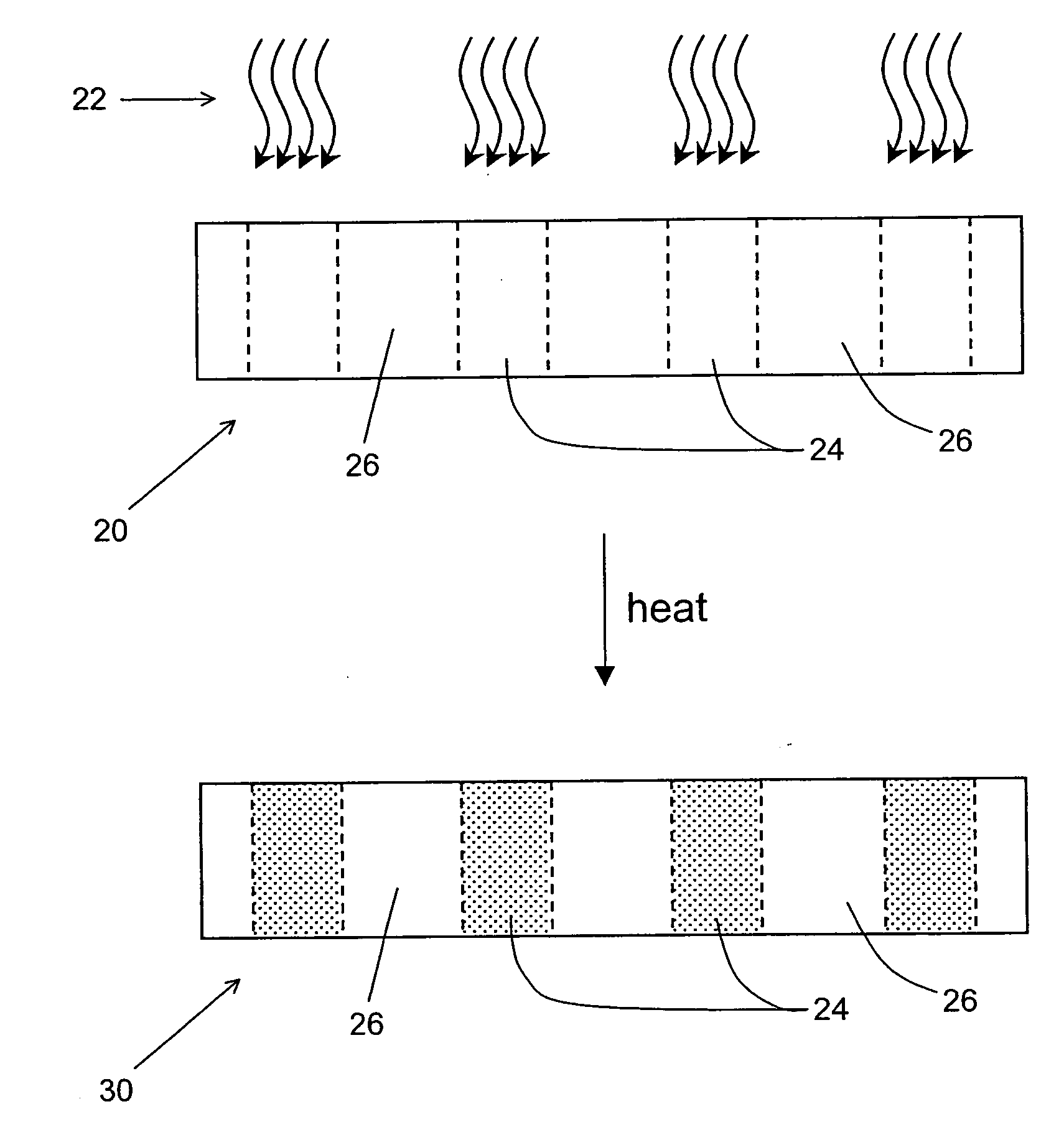
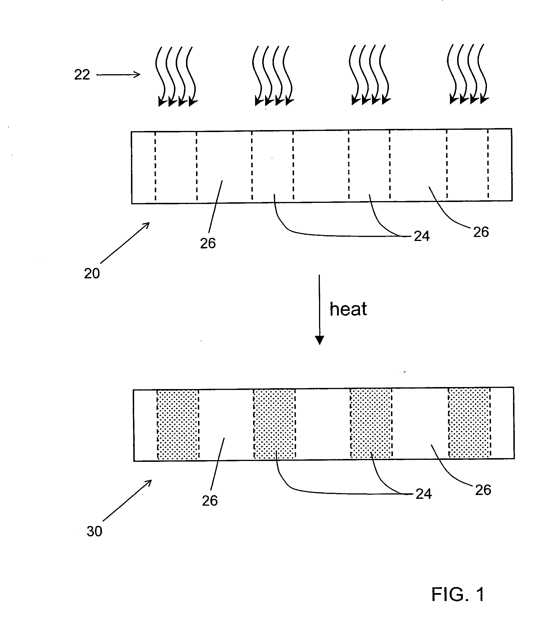
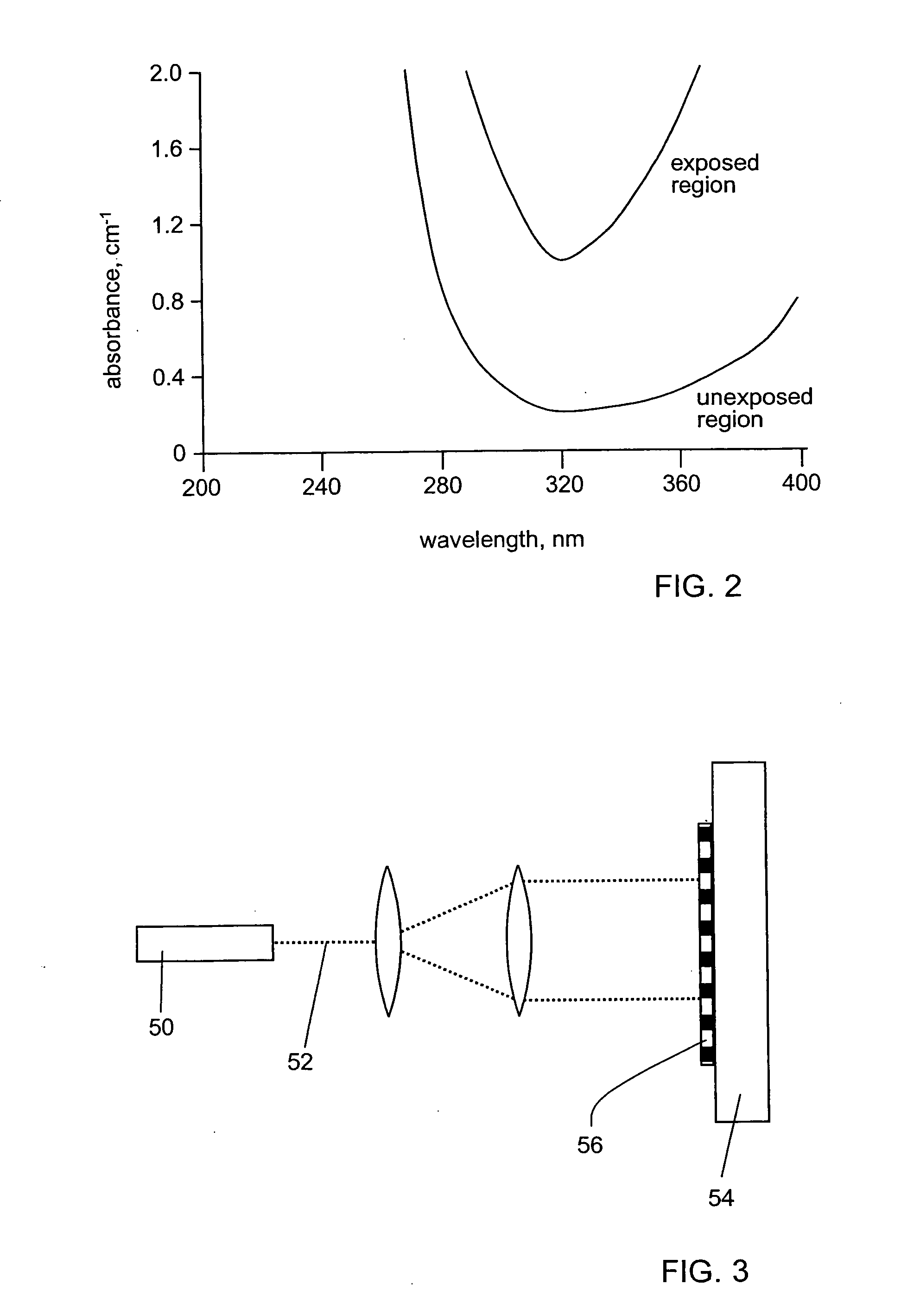
[0035]Glass material A of Example 1 was formed into a 1 mm thick slide. Part of the slide was exposed to 248 nm radiation from a KrF excimer laser for 6 minutes. The fluence per pulse was about 31 mJ / cm2, and the laser operated at a pulse rate of 50 Hz. The slide was then heat treated in a furnace at 540° C. for 5 minutes, and allowed to cool to room temperature. FIG. 2 shows absorption spectra of the exposed region and the unexposed region. The skilled artisan will note that the exposed region of the sample developed significantly more absorption than did the unexposed region.

example 3

[0036]Glass material A of Example 1 was formed into slides 1 mm in thickness. The slides were exposed as shown in FIG. 3. The output of a KrF excimer laser 50 operating at 248 nm and 50 Hz was expanded such that its fluence was 40 mJ / cm2 / pulse. A slide 54 of glass material A was exposed from its largest face 56 through a chrome absorption mask 52 having a 10 μm grating pitch. After exposure for a desired time, the slide was thrust into a furnace at a desired temperature, and allowed to remain there for a desired time. The slide was removed from the furnace and allowed to cool to room temperature. The grating was about 15 mm long.

[0037]The Bragg gratings so formed in the glass slides were illuminated from the edge of the slide with collimated 633 nm radiation. The diffraction efficiency was used to determine the index contrast between the exposed regions and unexposed regions of the Bragg gratings using the equation

efficiency=sin2(2πΔnLλ)

where λ is the wavelength of the illuminating ...


PUM

PropertyMeasurementUnit
peak wavelengthaaaaaaaaaa
melting temperatureaaaaaaaaaa
temperatureaaaaaaaaaa

Abstract

The present invention provides an optical element including a silver halide-containing glass material having a concentration of less than 0.001 wt % cerium; and a refractive index pattern formed in the silver halide-containing glass material, the refractive index pattern including regions of high refractive index and regions of low refractive index, the difference between the refractive indices of the high refractive index regions and the low refractive index regions being at least 4×10⁻⁵ at a wavelength of 633 nm. The present invention also provides methods for making optical elements from silver halide-containing glass materials.

Description

BACKGROUND OF THE INVENTION[0001]1. Field of the Invention[0002]The present invention relates generally to optical elements and methods for their manufacture, and more specifically to glass-based optical elements having a refractive index pattern formed therein, and methods for their manufacture.[0003]2. Technical Background[0004]Diffractive optical elements find use in a wide variety of fields. For example, diffractive optical elements are useful for filtering, beam shaping and light collection in display, security, defense, metrology, imaging and communications applications.[0005]One especially useful diffractive optical element is a Bragg grating. A Bragg grating is formed by a periodic modulation of refractive index in a transparent material. Bragg gratings reflect wavelengths of light that satisfy the Bragg phase matching condition, and transmit all other wavelengths. Bragg gratings are especially useful in telecommunications applications; for example, they have been used as se...

Claims


Application Information

Patent Timeline
Patent Type & Authority Applications(United States)
IPC IPC(8): C03C15/00G02B6/02H04B10/18
CPCG02B6/02009G02B6/02261H04B10/2525G02B6/03627G02B6/29377G02B6/02266
Inventor BORRELLI, NICHOLAS F.HARES, GEORGE B.SCHROEDER, JOSEPH F.
Owner CORNING INC
Why Eureka
Try Eureka