Photorefractive glass and optical elements made therefrom

a technology of photorefractive glass and optical elements, applied in the field of photorefractive glasses, can solve the problems of narrow-band filtering performance, inconvenient manufacturing, and inability to meet the requirements of many optical systems, and achieve the effect of high photoinduced refractive index changes and simplified manufacturing

Active Publication Date: 2007-10-30
CORNING INC
View PDF11 Cites 4 Cited by
  • Summary
  • Abstract
  • Description
  • Claims
  • Application Information

AI Technical Summary

Benefits of technology

[0015]The devices and methods of the present invention result in a number of advantages over prior art devices and methods. For example, the present invention provides a method suitable for the fabrication of bulk (i.e. not optical waveguide) Bragg grating devices. The method uses a photosensitive glass material that may be fabricated using conventional glass melting techniques, providing for simplified manufacture of a variety of shapes. The method may be performed using a conventional 248-nm laser exposure system. The optical elements of the present invention have high photoinduced refractive index changes that are stable at elevated temperatures.

Problems solved by technology

Many photosensitive materials have been used; however, few have provided the desired combination of performance and cost.
For example, Bragg gratings have been recorded in germanium-doped silica glass optical fibers; while such gratings are relatively robust, the fiber geometry and high melting point of the material make these gratings inappropriate for many optical systems.
These filters had narrow-band filtering performance, but suffered from low thermal stability, opacity in the UV region, and sensitivity to visible radiation after recording.
Photosensitive polymers have also been used as substrates for Bragg gratings; however, devices formed from polymeric materials tend to have high optical losses and high temperature sensitivity.
These glasses had very high absorbances at wavelengths less than 300 nm, making them unsuitable for use with commonly used 248 nm excimer laser exposure systems.

Method used


Image

  • Photorefractive glass and optical elements made therefrom
  • Photorefractive glass and optical elements made therefrom
  • Photorefractive glass and optical elements made therefrom

Examples


examples

[0040]The present invention is further described by the following non-limiting examples.

Example A-D

Glass Formation

[0041]The photosensitive glass materials for Example A-D listed in Table 2 were melted using methods familiar to the skilled artisan. Iota sand, boric acid, sodium chloride, sodium nitrate, sodium silicofluoride, antimony trioxide, zinc oxide and alumina were used as batch materials. The batched mixture was ball milled for 60 minutes, melted in platinum crucibles at temperatures of about 1425° C. for four hours, cast into slabs 4 inches wide and 1 inch thick, and annealed at 650° C. Concentrations are given in wt % on an as-batched basis.

[0042]

TABLE 2ABCDSiO269.3469.3169.2468.94Al2O36.656.646.646.60Na2O15.6015.5915.5815.51ZnO4.824.814.814.79Sb2O30.020.020.020.02SnO0.050.050.050.01Ag0.010.010.010.01F2.412.412.402.87Br1.061.061.061.05GeO200.10.20.19CeO20.05000

example a-d

Exposure Conditions

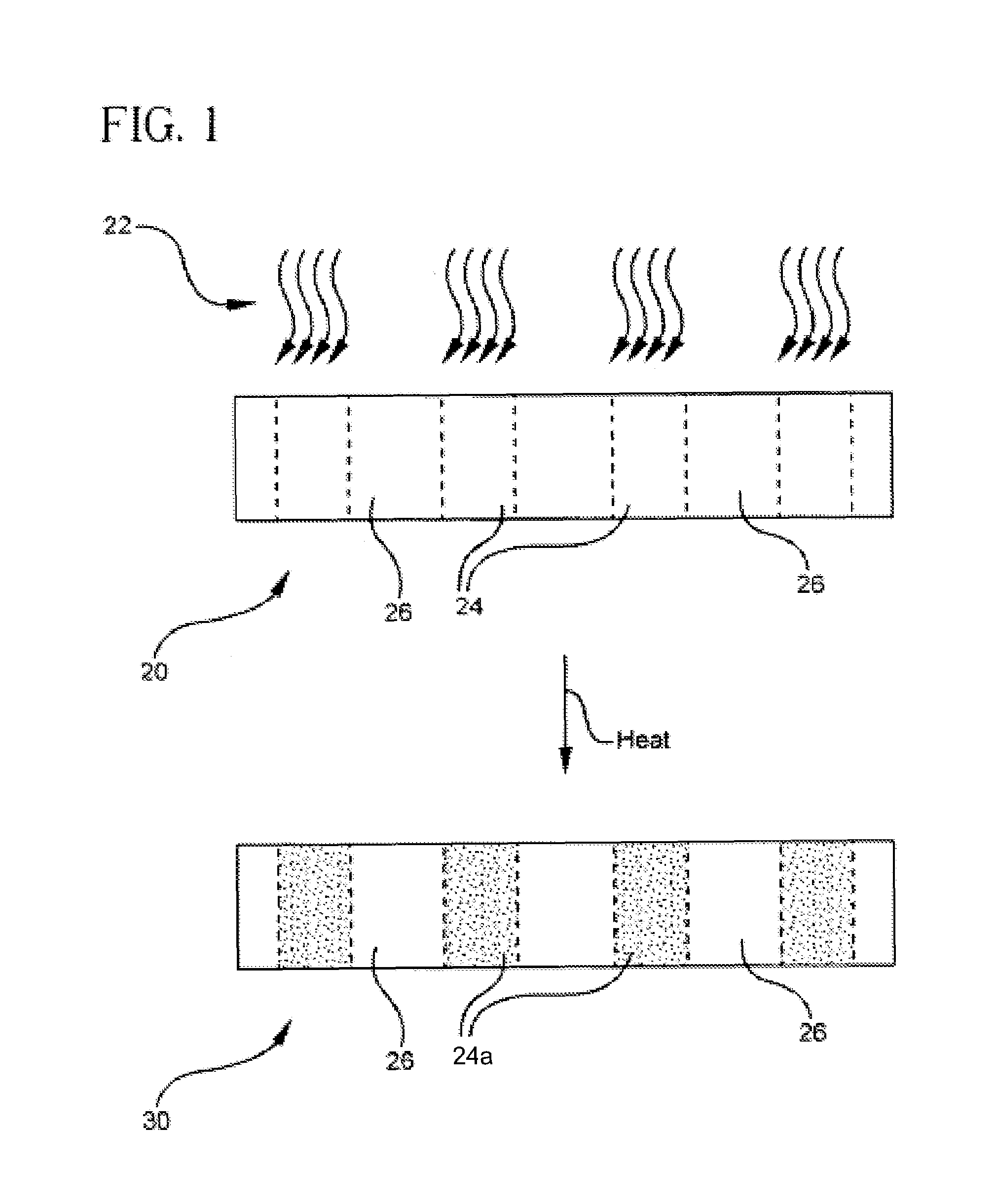
[0043]The so-formed glass material of Examples A-E was formed into 1-mm thick slides as described above. A portion of each slide was exposed to 248 nm radiation from a KrF excimer laser for times ranging from 6-20 minutes at 10 Hz. The fluence per pulse ranged between about 30-60 mJ / cm2. The slides were then heat treated in a furnace at 480-520° C. for approximately 2 hours, and allowed to cool to room temperature resulting in the formation of Bragg gratings.

[0044]The Bragg gratings so formed in the glass slides were illuminated from the edge of the slide with collimated 633 nm radiation. The diffraction efficiency was used to determine the index contrast between the exposed regions and unexposed regions of the Bragg gratings using the equation

[0045]efficiency=sin2⁡(2⁢πΔ⁢⁢nLλ)

where λ is the wavelength of the illuminating light, L is the thickness of the grating, and Δn is the index contrast between the exposed and unexposed regions of the grating. It follows that ...

example e

Exposure

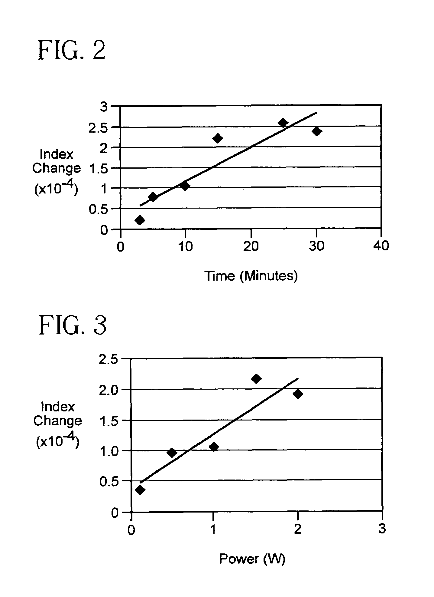
[0051]Glass material of the composition of Example E was actually formed into 6 slabs of the 4 inches wide and 1 inch thick dimension disclosed above. The 6 slabs were irradiated through a chrome absorption mask having a 10 μm grating pitch with the output of 355 nm radiation at average power of approximately 12 W at 10 Hz; the exposure times varied for the five samples from 3 to 30 minutes as detailed in Table 6. After irradiation, the samples were heat treated in a furnace at 550° C. for 2 hours to complete the formation of the Bragg gratings.

[0052]As above, the 6 Bragg gratings so formed in the glass slides were illuminated from the edge of the slide with collimated 633 nm radiation. The diffraction efficiency was again used to determine the index contrast between the exposed regions and unexposed regions of the Bragg gratings. The refractive index contrast (nexposed−nunexposed) data for various exposure times are given in Table 6 and plotted in FIG. 2. Like the samples A...


PUM

PropertyMeasurementUnit
wavelengthsaaaaaaaaaa

Abstract

The present invention provides an alkali alumino-silicate Na—F-containing glass material and a method of making the alkali alumino-silicate Na—F-containing glass material, with the glass material capable of being made photosensitive and thus formed into optical elements at wavelengths ranging between about 240 to 350 nm, and more particularly at the standard 248 nm wavelength of excimer lasers. Also disclosed is optical element wherein a refractive index pattern formed in the alumino-silicate Na—F containing glass material, the refractive index pattern including regions of high refractive index and regions of low refractive index, the difference between the refractive indices of the high refractive index regions and the low refractive index regions being at least 4×10⁻⁵ at a wavelength of 633 nm.

Description

CROSS-REFERENCE TO RELATED APPLICATION[0001]The present application claims priority to the U.S. Provisional Application with Ser. No. 60 / 533,859 filed on Dec. 31, 2003.BACKGROUND OF THE INVENTION[0002]1. Field of the Invention[0003]The present invention relates generally to photorefractive glasses, and more specifically to photorefractive glasses for use as glass-based optical elements having a refractive index pattern formed therein.[0004]2. Technical Background[0005]Diffractive optical elements find use in a wide variety of fields. For example, diffractive optical elements are useful for filtering, beam shaping and light collection in display, security, defense, metrology, imaging and communications applications.[0006]One especially useful diffractive optical element is a Bragg grating. A Bragg grating is formed by a periodic modulation of refractive index in a transparent material. Bragg gratings reflect wavelengths of light that satisfy the Bragg phase matching condition, and tr...

Claims


Application Information

Patent Timeline
Patent Type & Authority Patents(United States)
IPC IPC(8): C03C3/112C03C4/00C03C6/02C03C4/04G02B5/00G02B6/00G02B6/12
CPCC03C3/112C03C4/04C03C4/0071G02B2006/12107
Inventor SCHROEDER, JOESEPH FBORRELLI, NICHOLAS FHARES, GEORGE B
Owner CORNING INC
Why Eureka
Try Eureka