Image forming apparatus and method of controlling same

a technology of which is applied in the direction of digital output to print units, visual presentation using printers, instruments, etc., can solve the problems of large power consumption, comparatively large amount of power consumption, and large power consumption in power saving mode, so as to improve the image forming apparatus and control method.

Active Publication Date: 2011-02-22
CANON KK
View PDF22 Cites 25 Cited by
  • Summary
  • Abstract
  • Description
  • Claims
  • Application Information

AI Technical Summary

Benefits of technology

[0016]Accordingly, an object of the present invention is to provide an improved image forming apparatus and method of controlling same.
[0017]Another object of the present invention is to provide an image forming apparatus and method of controlling same in which the power-saving effect is enhanced by so arranging it that a transition from the power save mode to the power supply mode is performed more appropriately.
[0018]According to one aspect of the present invention, there is provided an image forming apparatus comprising: a first receiving unit adapted to receive data transmitted from an external apparatus; an interpreting unit adapted to interpret content of data received by the first receiving unit; a printing unit adapted to execute print processing based upon print data if the print data has been received by the first receiving unit; and an operating-status control unit adapted to execute control in such a manner that the interpreting unit is placed in an active state or inactive state, wherein in response to receipt of data by the first receiving unit, the operating-status control unit causes the interpreting unit, which is in the inactive state, to transition to a first operating state, and causes the interpreting unit to transition from the first operating state to a second operating state, in which power consumption is greater, in response to an interpretation by the interpreting unit that content of the data is print data.

Problems solved by technology

A problem, therefore, is that a comparatively large amount of power is consumed.
Power is consumed as a result.
Ultimately, consumption of power in the power save mode is great, just as in the case of Japanese Patent Application Laid-Open No. 8-324071.

Method used


Image

  • Image forming apparatus and method of controlling same
  • Image forming apparatus and method of controlling same
  • Image forming apparatus and method of controlling same

Examples


Embodiment Construction

[0029]The present invention will now be described in detail with reference to the drawings showing an embodiment thereof.

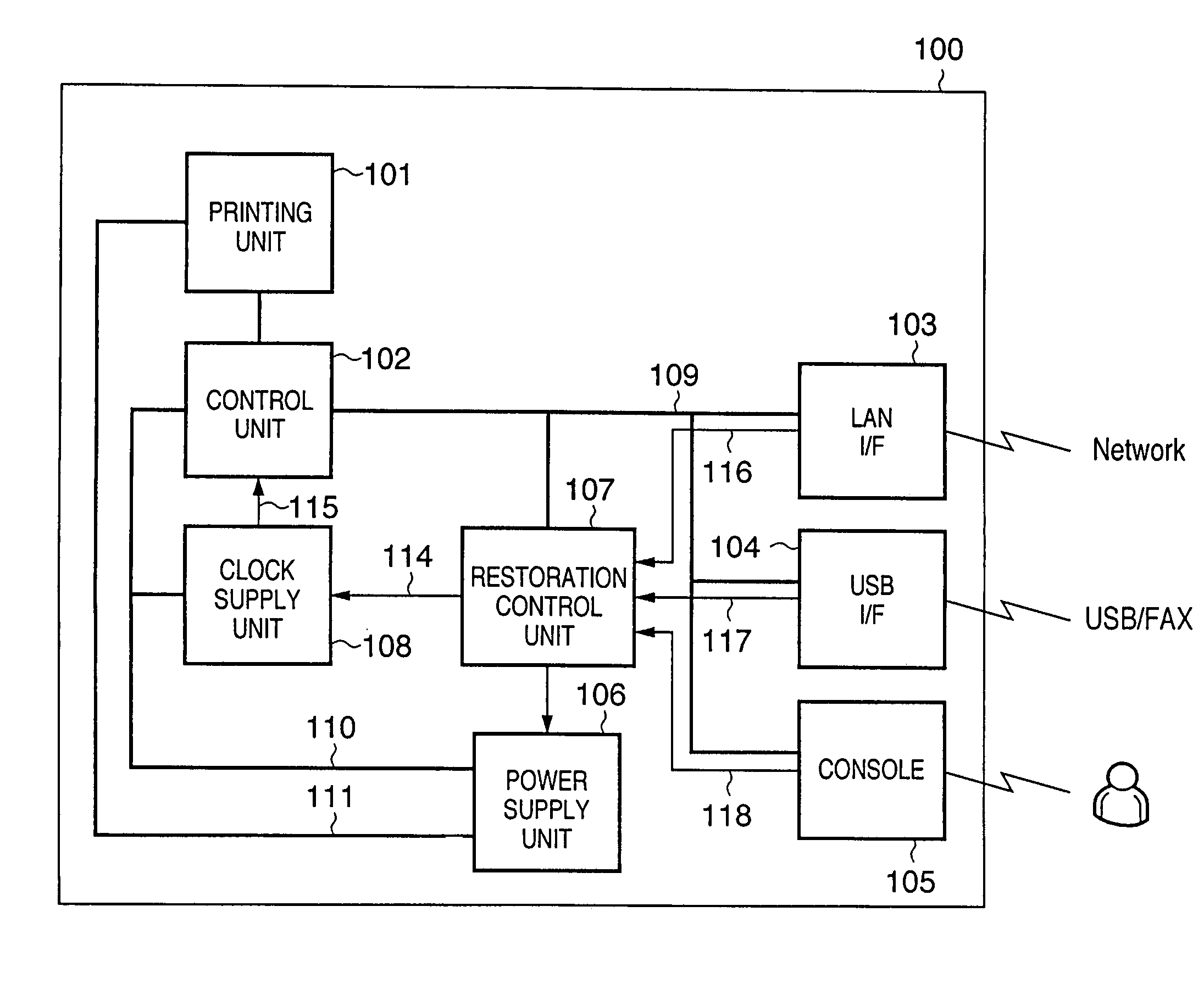
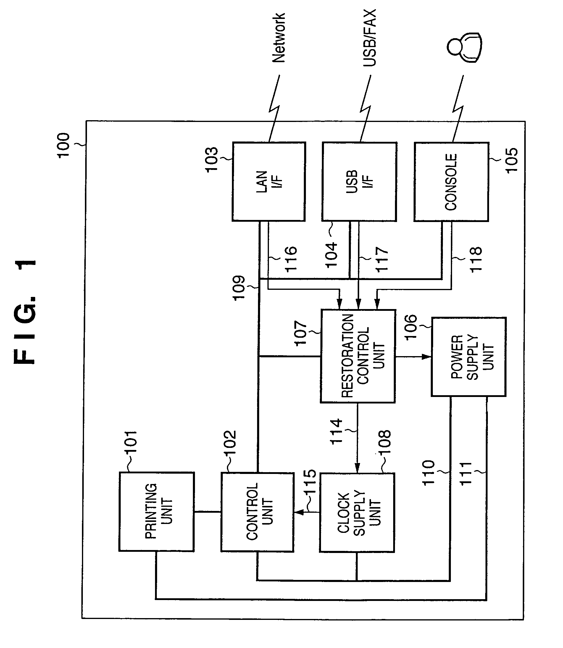
[0030]FIG. 1 is a block diagram illustrating the structure of an image forming apparatus (printing apparatus) according to an embodiment of the present invention. As shown in FIG. 1, an image forming apparatus 100 includes a printing unit 101 for printing an image on paper, a control unit 102 for controlling the overall apparatus, and a power supply unit 106 for supplying power to each component of the apparatus. The apparatus further includes a network interface 103 (e.g. LAN I / F), a serial interface 104 (e.g. USB I / F) and a console 105 for interfacing external equipment or the user. Signals from outside the apparatus are received by the image forming apparatus 100 via any of the plurality of interfaces 103 to 105.

[0031]A restoration control unit 107 outputs a drive command signal to the power supply unit 106 and to a clock supply unit 108 in accordance with dete...


PUM


Abstract

A image forming apparatus 100 has a network interface 103 for receiving data transmitted from an external apparatus, and a control unit 102 for interpreting content of data received by the network interface 103. The image forming apparatus 100 further has a printing unit 101 for executing print processing based upon print data if print data has been received by the network interface 103, and a restoration control unit 107 for exercising control so as to place the control unit 102 in an active state or inactive state. The restoration control unit 107 of the image forming apparatus 100 starts supplying a low-speed clock to the control unit 102 in the inactive state in response to receipt of data by the network interface 103, and starts supplying a high-speed clock in response to an interpretation by the control unit 102 that the content of the data is print data.

Description

BACKGROUND OF THE INVENTION[0001]1. Field of the Invention[0002]The present invention relates to an image forming apparatus and to a method of controlling this apparatus.[0003]2. Description of the Related Art[0004]An image forming apparatus such as a copier or multi-functional peripheral generally comprises a plurality of subsystems such as a main controller for controlling the overall image forming apparatus, a scanner for reading in an image and a printer for forming an image on paper. It has become commonplace, in recent years for such an image forming apparatus to be connectable to a network. A network-connected image forming apparatus receives print data, which has been transmitted from a plurality of personal computers or servers, via a network, and performs printing in accordance with the print data received.[0005]Further, if the image forming apparatus is not issued an operation request in excess of a fixed period of time, control is exercised to automatically cut off the s...

Claims


Application Information

Patent Timeline
Patent Type & Authority Patents(United States)
IPC IPC(8): G06K15/22G06K15/10G06F1/00G06F1/26G06F1/32
CPCG03G15/5004G06K15/02H04N1/00885G03G15/5087H04N1/00896H04N1/00891H04N2201/0091H04N2201/0094
Inventor MAEDA, TADAAKI
Owner CANON KK
Why Eureka
Try Eureka