
Method for determining earth vertical electrical anisotropy in marine electromagnetic surveys

a technology of electromagnetic surveys and vertical electrical anisotropy, which is applied in the direction of reradiation, detection using electromagnetic waves, instruments, etc., can solve the problems of not being used for offshore hydrocarbon applications, affecting interpretation, and much lower efficiency (poor coupling) than hed sources

Active Publication Date: 2011-02-22
EXXONMOBIL UPSTREAM RES CO
View PDF23 Cites 20 Cited by
  • Summary
  • Abstract
  • Description
  • Claims
  • Application Information

AI Technical Summary

Benefits of technology

The invention is a computer-based method for determining the electrical properties of the earth's subsurface layers using data collected from an electromagnetic survey. The method involves measuring the electromagnetic field at different locations in the subsurface and analyzing the data to calculate the resistivities of the layers. This allows for the determination of the vertical electrical anisotropy, which is important for understanding the structure and properties of the subsurface. The method can be used in offshore environments and is useful for oil and gas exploration.

Problems solved by technology

This distortion affects the interpretation of marine CSEM resistivity anomalies associated with the presence of reservoired hydrocarbons.
HMD sources also produce both vertical and horizontal electrical currents, but to date have not been used for offshore hydrocarbon applications because of their low power and other operational constraints.
The vertical electric dipole (“VED”) method (Edwards, et al., J. Geophys. Res. 86B, 11609-11615 (1981)) produces primarily vertical currents in the earth, but with much lower efficiency (poorer coupling) than HED sources.
The vertical magnetic dipole (“VMD”) source produces essentially only horizontal earth currents, and to date has also not been used in marine CSEM surveys due to operational disadvantages.

Method used


Image

  • Method for determining earth vertical electrical anisotropy in marine electromagnetic surveys
  • Method for determining earth vertical electrical anisotropy in marine electromagnetic surveys
  • Method for determining earth vertical electrical anisotropy in marine electromagnetic surveys

Examples


examples

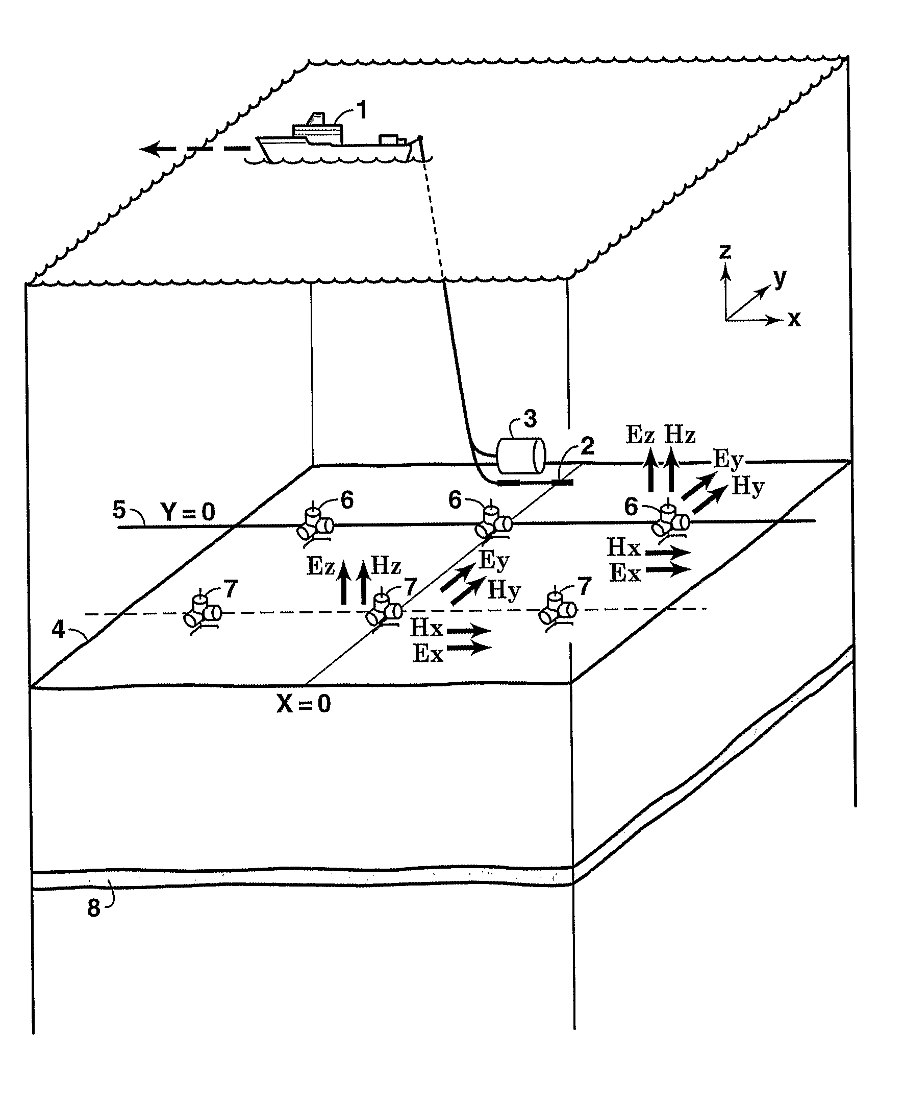
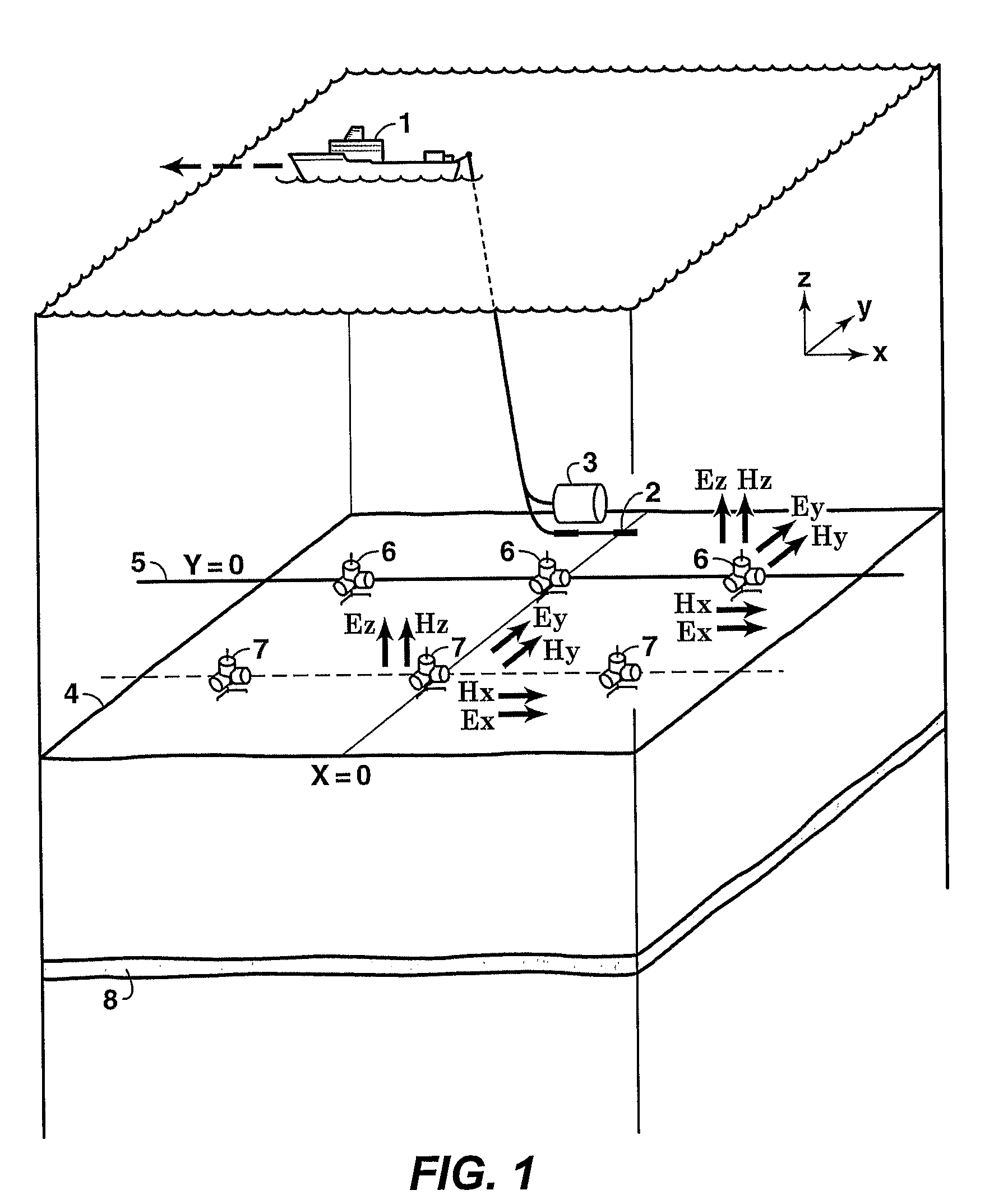
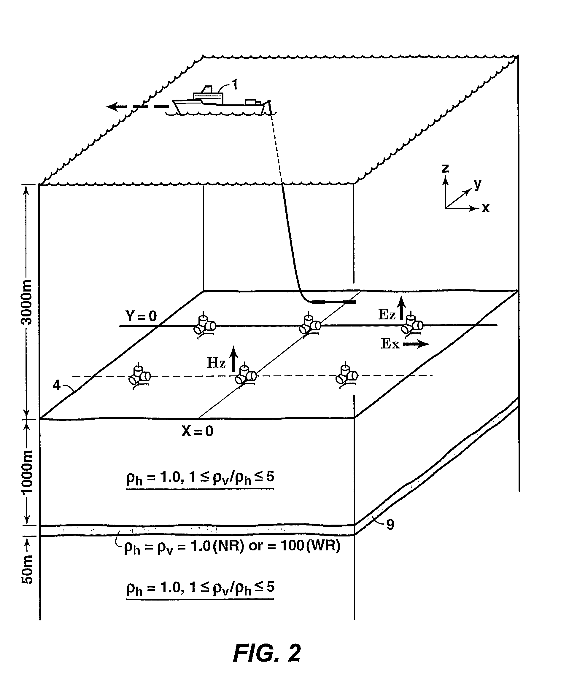
[0043]In lieu of actual CSEM data of the type and combination required in this invention, numerical calculations that employ 1D methods well known to practitioners of the art are used herein to demonstrate the EVTI responses utilized by the invention. FIG. 2 shows the survey geometry used for this model calculation of CSEM response data. The example uses a seawater depth of 3000 meters and a 50 meter thick, simulated hydrocarbon reservoir 9 buried 1000 meters below the seafloor 4. FIGS. 3A and 3B show the calculated changes in the HED source-normalized (i.e., responses for a unit dipole of length one meter and current of one Ampere) online Ex seafloor field amplitudes in volts / m (FIG. 3A) and the absolute phases (FIG. 3B) caused by EVTI of varying magnitudes (1:1 to 5:1 EVTI ratio ρv:ρh, where ρv is the vertical resistivity and ρh is the horizontal resistivity), corresponding to the survey geometry and earth parameters of FIG. 2 for a sinusoidal source frequency of 0.25 Hertz. The a...


PUM


Abstract

A method is disclosed for determining earth vertical electrical anisotropy from offshore electromagnetic survey measurements. The method requires both online and offline data, which includes at least one electromagnetic field component sensitive at least predominantly to vertical resistivity and another component sensitive at least predominantly to horizontal resistivity. Using a horizontal electric dipole source, online EZ and offline HZ measurements are preferred. For a horizontal magnetic dipole source, online HZ and offline EZ data are preferred. magnetotelluric data may be substituted for controlled source data sensitive to horizontal resistivity. Maxwell's equations are solved by forward modeling or by inversion, using resistivity models of the subsurface that are either isotropic or anisotropic.

Description

[0001]This application claims the benefit of U.S. Provisional Patent Application No. 60 / 688,841 filed on Jun. 9, 2005.FIELD OF THE INVENTION[0002]This invention relates generally to the field of controlled-source electromagnetic surveys in offshore environments, in which a controlled electromagnetic transmitter is towed above or positioned between electromagnetic receivers on the sea floor, for the purposes of hydrocarbon exploration, development, and / or production. Specifically, the invention is a method for determining the difference between the earth's resistivity at a given location as measured using a horizontal current flow compared to that measured with a vertical current.BACKGROUND OF THE INVENTION[0003]Results from offshore controlled-source electromagnetic (“CSEM”) surveys, such as those collected using the methods disclosed in U.S. Pat. No. 6,603,313 to Srnka and U.S. Patent Publication No. 2003 / 0050759 published Mar. 13, 2003 (Srnka, et al.), have shown that the resistiv...

Claims


Application Information

Patent Timeline
Patent Type & Authority Patents(United States)
IPC IPC(8): G01V3/00G01V1/28
CPCG01V3/12G01V3/083
Inventor SRNKA, LEONARD J.LU, XINYOUBURTZ, OLIVIER M.
Owner EXXONMOBIL UPSTREAM RES CO
Learn More