Rotary drag bits having a pilot cutter configuraton and method to pre-fracture subterranean formations therewith

a pilot cutter and drag bit technology, which is applied in the direction of drilling machines, cutting machines, methods, etc., can solve the problems of reducing the penetration rate, and reducing so as to prolong the life of cutting elements and improve the fracturing of subterranean formation materials , the effect of improving the life of rotary bits

Active Publication Date: 2011-03-01
BAKER HUGHES INC
View PDF69 Cites 12 Cited by
  • Summary
  • Abstract
  • Description
  • Claims
  • Application Information

AI Technical Summary

Benefits of technology

[0010]Accordingly, a rotary drag bit having a pilot cutter configuration is provided. The rotary drag bit life is extended by the pilot cutter configuration, making the bit more durable and extending the life of the cutting elements. Further, the pilot cutter configuration on the rotary drag bit improves fracturing of subterranean formation material being drilled, providing improved bit life and reduced stress upon the cutters.
[0012]In other embodiments of the invention, a rotary drag bit having improved life is provided. The rotary drag bit comprises a bit body and at least one cutter set comprising a pilot cutter and a rotationally trailing primary cutter coupled to the bit body.

Problems solved by technology

While the PDC cutting element improves drill bit efficiency in drilling many subterranean formations, however, the PDC cutting element is nonetheless prone to wear when operationally exposed to drilling conditions and lessens the life of a rotary bit.
The decrease in the penetration rate is a manifestation that the rotary drag bit is wearing out, particularly when other drilling parameters remain constant.
While researchers continue to develop and seek out improvements for longer lasting cutters or generalized improvements to cutter performance, they fail to accommodate or implement an engineered approach to achieving longer drag bit life by maintaining or increasing penetration rate or ROP by taking advantage of cutting element wear rates.

Method used


Image

  • Rotary drag bits having a pilot cutter configuraton and method to pre-fracture subterranean formations therewith
  • Rotary drag bits having a pilot cutter configuraton and method to pre-fracture subterranean formations therewith
  • Rotary drag bits having a pilot cutter configuraton and method to pre-fracture subterranean formations therewith

Examples


first embodiment

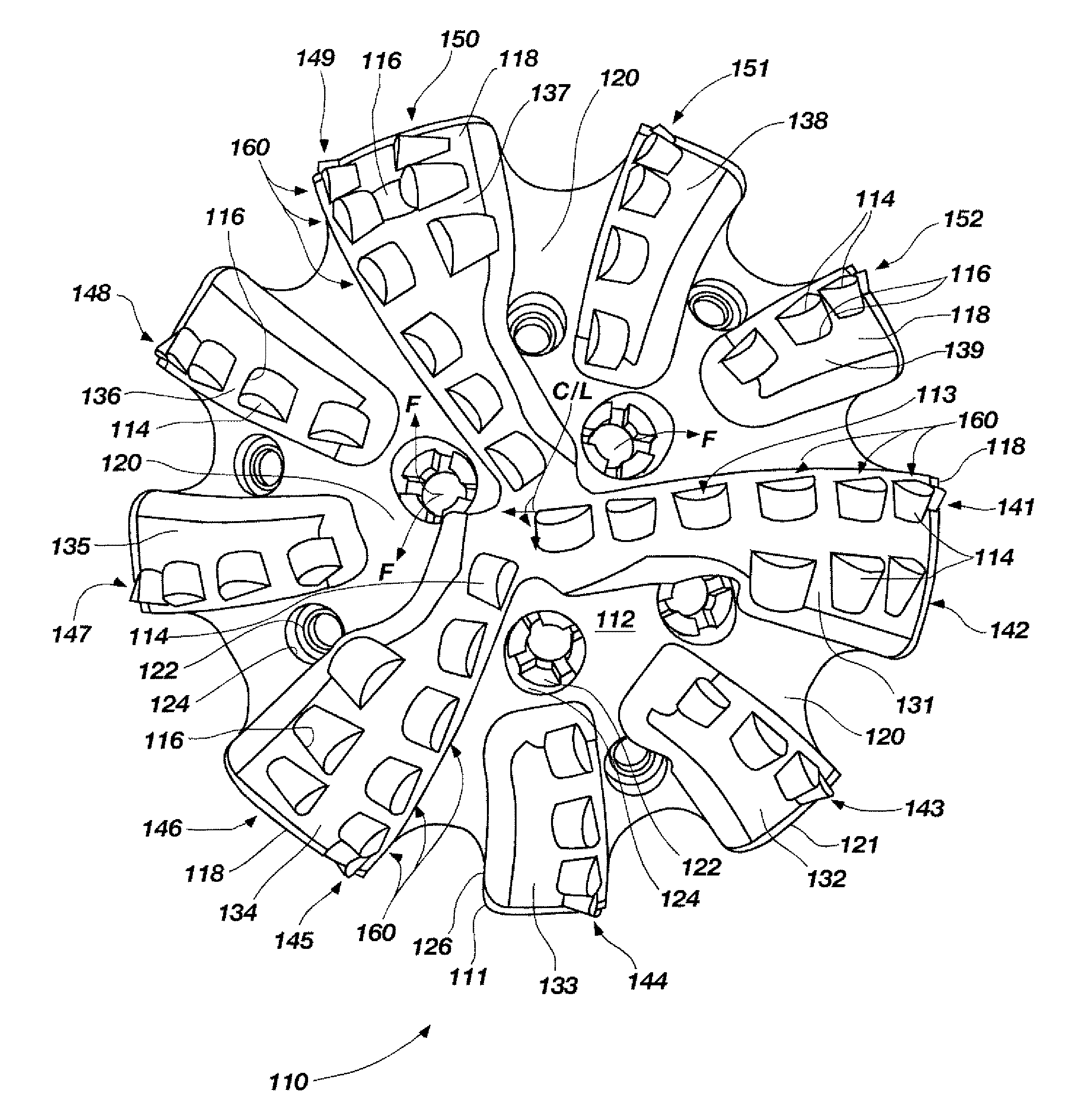
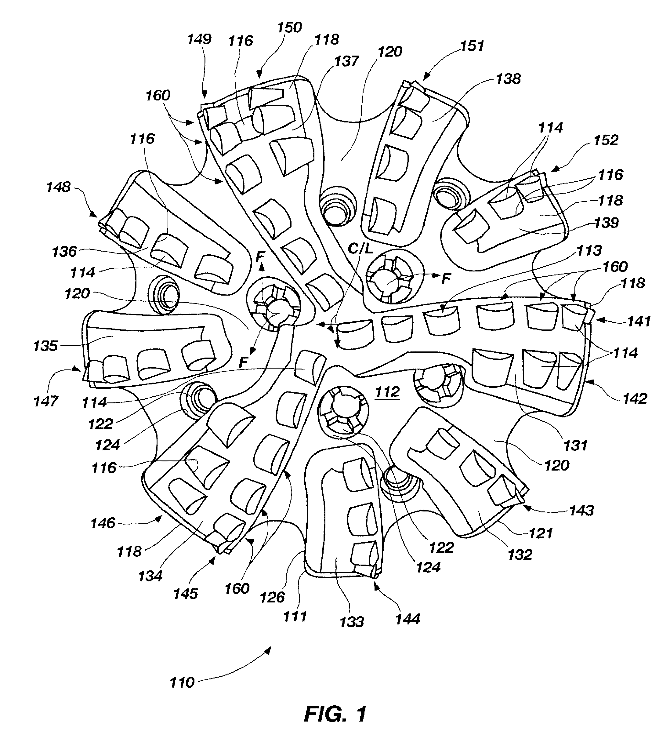
[0029]FIG. 1 shows a face view of a rotary drag bit 110 in accordance with the invention. While the rotary drag bit 110 of this embodiment comprises nine pilot or cutter sets 160, it is contemplated that the drag bit 110 may include one cutter set or a plurality of cuter combination sets greater or less than the nine illustrated. Before turning to a detailed description of the cutter sets 160, the general description of the drag bit 110 is first discussed.

[0030]The rotary drag bit 110 as viewed by looking upwardly at its face or leading end 112 as if the viewer were positioned at the bottom of a bore hole. Bit 110 includes a plurality of cutting elements or cutters 114 bonded, as by brazing, into pockets 116 (as representatively shown) located in the blades 118 extending above the face 112 of the drag bit 110, as is well known to those of ordinary skill in the art. The drag bit 110 depicted is a matrix body bit, but the invention is not so limited. The bit may also be formed as a so...

third embodiment

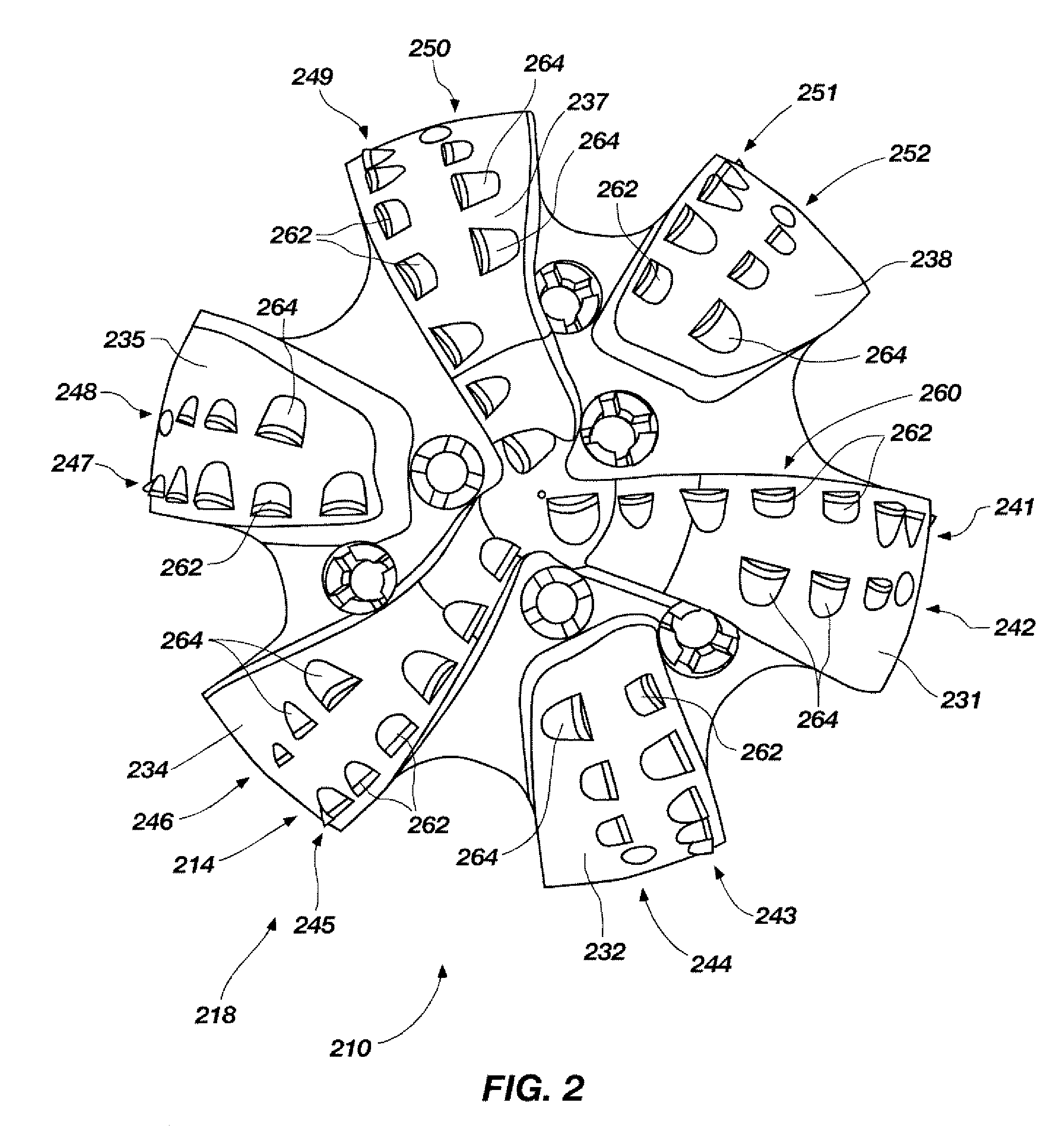
[0041]FIG. 7A shows a cutter profile 330 for a bit 310 having a cutter set 360 in accordance with the invention. The cutter set 360 includes a first cutter 362 and a second cutter 364, both being coupled to a bit body 311 of the bit 310. The second cutter 364 is larger than the first cutter 362, and is underexposed with respect to and rotationally trails the first cutter 362. While the second cutter 364 rotationally trails the first cutter 362, it need only rotationally trail in a substantially adjacent or similar rotational or helical path created by the rotation of the bit 310. Assuming that the applied force for fracturing the formation is held constant upon the bit 310, the first cutter 362 may apply greater stress upon the formation because of its smaller face surface area 363 and engaged cutting edge in comparison to the second cutter 364 with its larger face surface area 365. In this regard, the first cutter 362 may provide the primary force for pre-fracturing a formation due...


PUM


Abstract

A rotary drag bit exhibiting enhanced cutting efficiency and extended life is provided. The rotary drag bit comprises a bit body having a face surface, and a plurality of cutters coupled to the face surface of the bit body. The plurality of cutters comprises at least one pilot cutter and a rotationally trailing larger, primary cutter at substantially the same radius and, optionally of slightly less exposure. The pilot cutter is sized and positioned to pre-fracture the formation and perform an initial cut, while the primary cutter removes weakened, remaining formation material along the same rotational path. A method to pre-fracture subterranean formations using a rotary drag bit having a pilot cutter configuration is also provided.

Description

CROSS-REFERENCE TO RELATED APPLICATION[0001]This application claims the benefit of the filing date of U.S. Provisional Patent Application Ser. No. 60 / 873,349, filed Dec. 7, 2006, for “ROTARY DRAG BITS HAVING A PILOT CUTTER CONFIGURATION AND METHOD TO PRE-FRACTURE SUBTERRANEAN FORMATIONS THEREWITH,” the entire contents of which is hereby incorporated herein by this reference.[0002]This application is also related to U.S. patent application Ser. No. 12 / 019,814, filed Jan. 25, 2008, for ROTARY DRAG BIT, which claims the benefit of U.S. Provisional Patent Application Ser. No. 60 / 897,457 filed Jan. 25, 2007, for ROTARY DRAG BIT. This application is also related to U.S. patent application Ser. No. 12 / 020,399, filed Jan. 25, 2008, for ROTARY DRAG BIT AND METHODS THEREFOR, which claims the benefit of U.S. Provisional Patent Application Ser. No. 60 / 897,457 filed Jan. 25, 2007, for ROTARY DRAG BIT. This application is also related to U.S. patent application Ser. No. 12 / 020,492, filed Jan. 25,...

Claims


Application Information

Patent Timeline
Patent Type & Authority Patents(United States)
IPC IPC(8): E21B10/26E21B10/43
CPCE21B10/43E21B10/54
Inventor GAVIA, DAVID
Owner BAKER HUGHES INC
Why Eureka
Try Eureka