
Circuit board and manufacturing method thereof

a technology of circuit board and manufacturing method, which is applied in the direction of electrical apparatus construction details, electrical apparatus casings/cabinets/drawers, cross-talk/noise/interference reduction, etc., can solve the problems of increasing the difficulty of circuit board assembly, and achieve the effect of reducing cost, sufficient strength and simplifying the manufacturing process

Active Publication Date: 2011-03-01
GIGA BYTE TECH CO LTD
View PDF8 Cites 18 Cited by
  • Summary
  • Abstract
  • Description
  • Claims
  • Application Information

AI Technical Summary

Benefits of technology

The patent describes a circuit board design that eliminates the need for expensive and complicated annular conductive pads, resulting in cost savings and a simplified manufacturing process. The circuit board includes a substrate, a first conductive layer, at least one through hole, a protection layer, and a plurality of contacts. The contacts are formed during the manufacturing process and are protruding from the surface of the protection layer. The circuit board is fixed in a through hole using a fixing element that contacts the contacts. The contacts provide sufficient strength to resist pressure from the fixing element, preventing scratches on the circuit board. The contacts can withstand pressure of 12 kg / cm2.

Problems solved by technology

Additionally, during assembly, the annular conductive pads 21 are easily displaced or detached, which increase difficulty of circuit board assembly.

Method used


Image

  • Circuit board and manufacturing method thereof
  • Circuit board and manufacturing method thereof
  • Circuit board and manufacturing method thereof

Examples


Embodiment Construction

[0020]The following description is of the best-contemplated mode of carrying out the invention. This description is made for the purpose of illustrating the general principles of the invention and should not be taken in a limiting sense. The scope of the invention is best determined by reference to the appended claims.

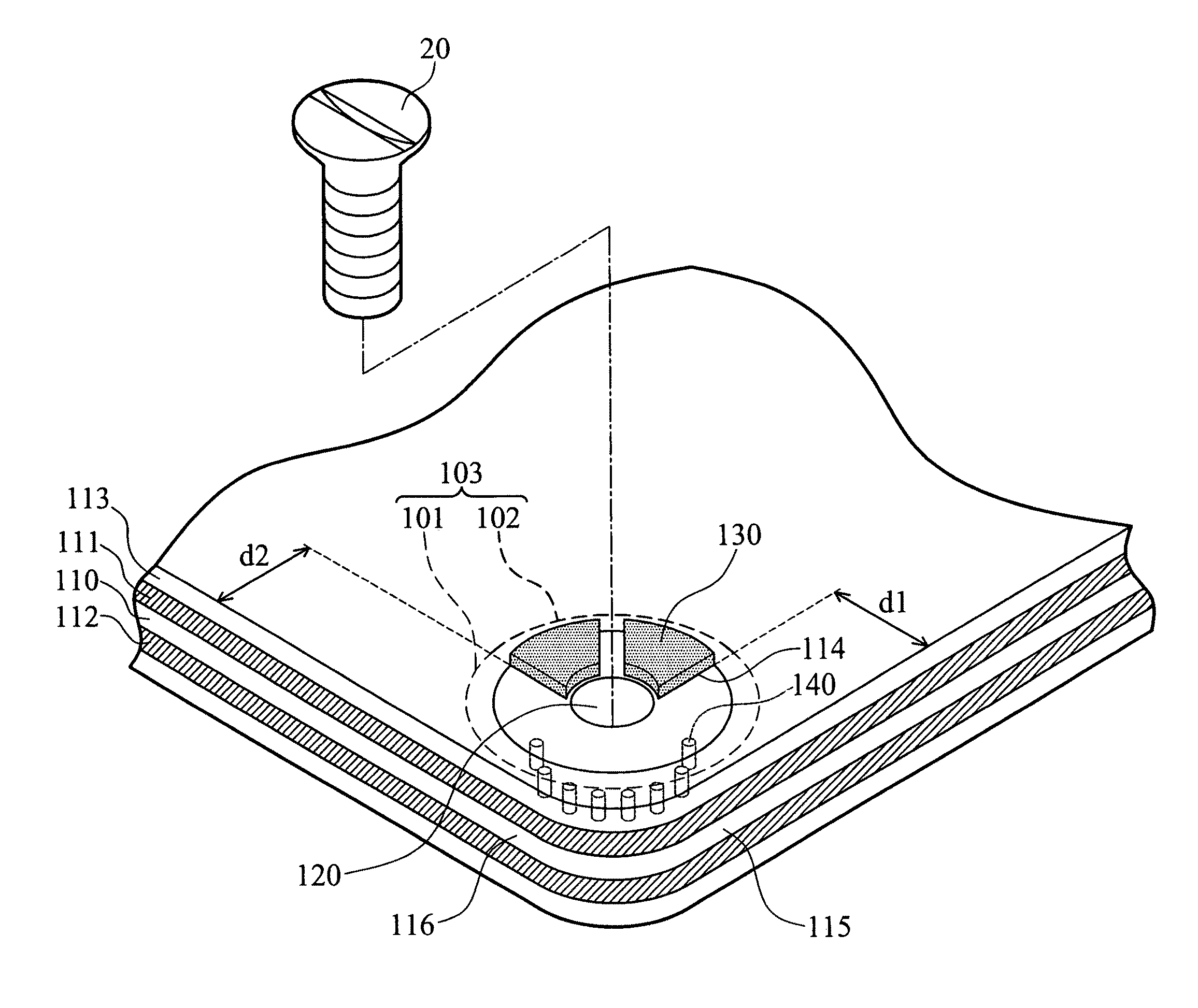
[0021]FIG. 2 shows a circuit board 100 of the invention comprising a substrate 110, a plurality of through holes 120 and a plurality of fixing elements 20. FIG. 3 is an enlarged view of portion B in FIG. 2, wherein the circuit board 100 further comprises a first conductive layer 111, a second conductive layer 112, a production layer 113 and contacts 130. The first conductive layer 111 and the second conductive layer 112 are formed on the surfaces of the substrate 110, and separated thereby. The through hole 120 passes through the substrate 110, the first conductive layer 111, the second conductive layer 112 and the protection layer 113. The protection layer 113 is form...


PUM

PropertyMeasurementUnit
holding reserve distanceaaaaaaaaaa
distance d2aaaaaaaaaa
conductiveaaaaaaaaaa

Abstract

A circuit board is provided, comprising a substrate, a first conductive layer, at least one through hole, a protection layer, a plurality of contacts and a fixing element. The first conductive layer is formed on the substrate. The through hole is formed on the substrate and the first conductive layer. The protection layer is formed on the first conductive layer, wherein the protection layer comprises a plurality of hollow portions, the hollow portions surround the through hole, and the first conductive layer is exposed in the hollow portions. The contacts are disposed in the hollow portions, wherein the contacts are protruding from a surface of the protection layer. The fixing element is fixed in the through hole, wherein the fixing element contacts the contacts.

Description

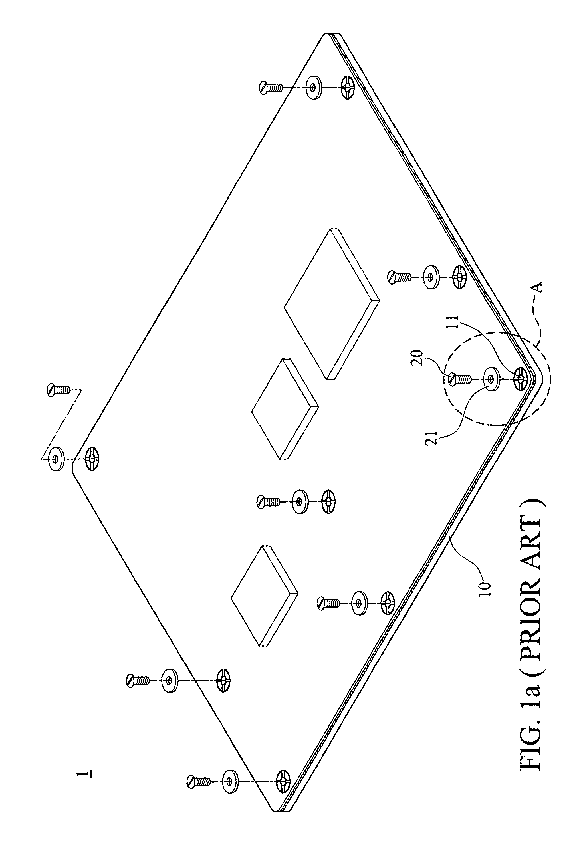
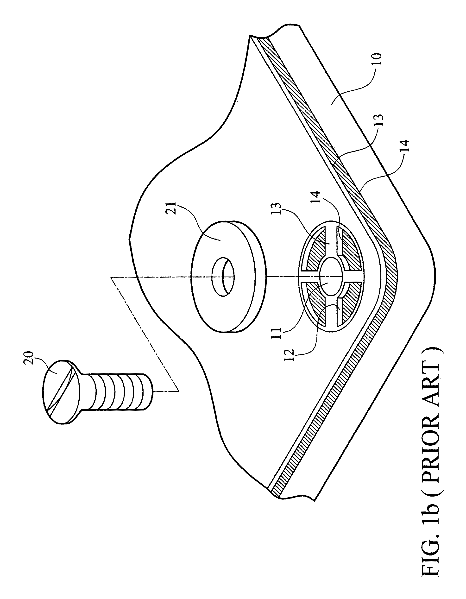
BACKGROUND OF THE INVENTION[0001]1. Field of the Invention[0002]The invention relates to a circuit board, and more particularly to an easy to assemble circuit board.[0003]2. Description of the Related Art[0004]FIG. 1a shows a conventional circuit board 1 comprising a substrate 10, a plurality of through holes 11, a plurality of fixing elements 20 and a plurality of annular conductive pads 21. FIG. 1b is an enlarged view of portion A in FIG. 1a, wherein a protection layer 13 and a conductive layer 14 are formed on the substrate 10. The protection layer 13 comprises hollow portions 12 surrounding the through hole 11. The conductive layer 14 is exposed in the hollow portions 12. When the fixing element 20 is fixed in the through hole 11, the annular conductive pad 21 is sandwiched between the fixing element 20 and the substrate 10. The annular conductive pad 21 contacts the conductive layer 14 exposed in the hollow portions 12 to electrically connect the conductive layer 14 and the fix...

Claims


Application Information

Patent Timeline
Patent Type & Authority Patents(United States)
IPC IPC(8): H05K7/02H05K7/04
CPCH05K1/0215H05K1/116H05K3/325H05K7/142H05K3/3452H05K3/3484Y10T29/49124H05K2201/09063H05K2201/0979H05K2201/10409H05K2203/043H05K3/3485
Inventor KAO, YUNG-SHUNCHUNG, HUI-LINGLU, YU-CHIANGCHIANG, CHUNG-WEI
Owner GIGA BYTE TECH CO LTD
Learn More