
Low latency multicast for infiniband® host channel adapters

a host channel adapter and low latency technology, applied in the field of computer system communication, can solve the problems of large time consumption of typical data exchange between system memory and infiniband® adapters, and achieve the effects of minimizing communication, reducing latency reception, and improving cache coherency

Inactive Publication Date: 2011-03-01
IBM CORP
View PDF25 Cites 24 Cited by
  • Summary
  • Abstract
  • Description
  • Claims
  • Application Information

AI Technical Summary

Benefits of technology

The present invention provides a computer system with receive queues implemented in host system memory where message data and work completion information are provided to the system in a single transfer over the processor local bus. This reduces latency reception by minimizing communication back and forth between the hardware adapter and memory. The invention also provides a hardware adapter coupled to the host system and network fabric for transferring data messages, which includes a QP Context identifying RQ status, storage buffers, and a CQE information as the work completion information. The host system receives data transfers from the adapter comprising CQE information and payload data, and the adapter receives network packets each containing header information sufficient for the adapter to build a corresponding data message to the system comprising the CQE information and data, and also to provide the standard protection checks required by the IB architecture. The receive queue includes a plurality of uniformly sized slots equivalent to the size of a single cache line as architected in the host system, and each data message begins on a slot boundary with its CQE portion, followed by the data portion. These technical effects improve the efficiency and reliability of the computer system.

Problems solved by technology

Typical data exchanges between system memory and InfiniBand® adapters that are required to receive messages consume sizeable amounts of time.

Method used


Image

  • Low latency multicast for infiniband® host channel adapters
  • Low latency multicast for infiniband® host channel adapters
  • Low latency multicast for infiniband® host channel adapters

Examples


Embodiment Construction

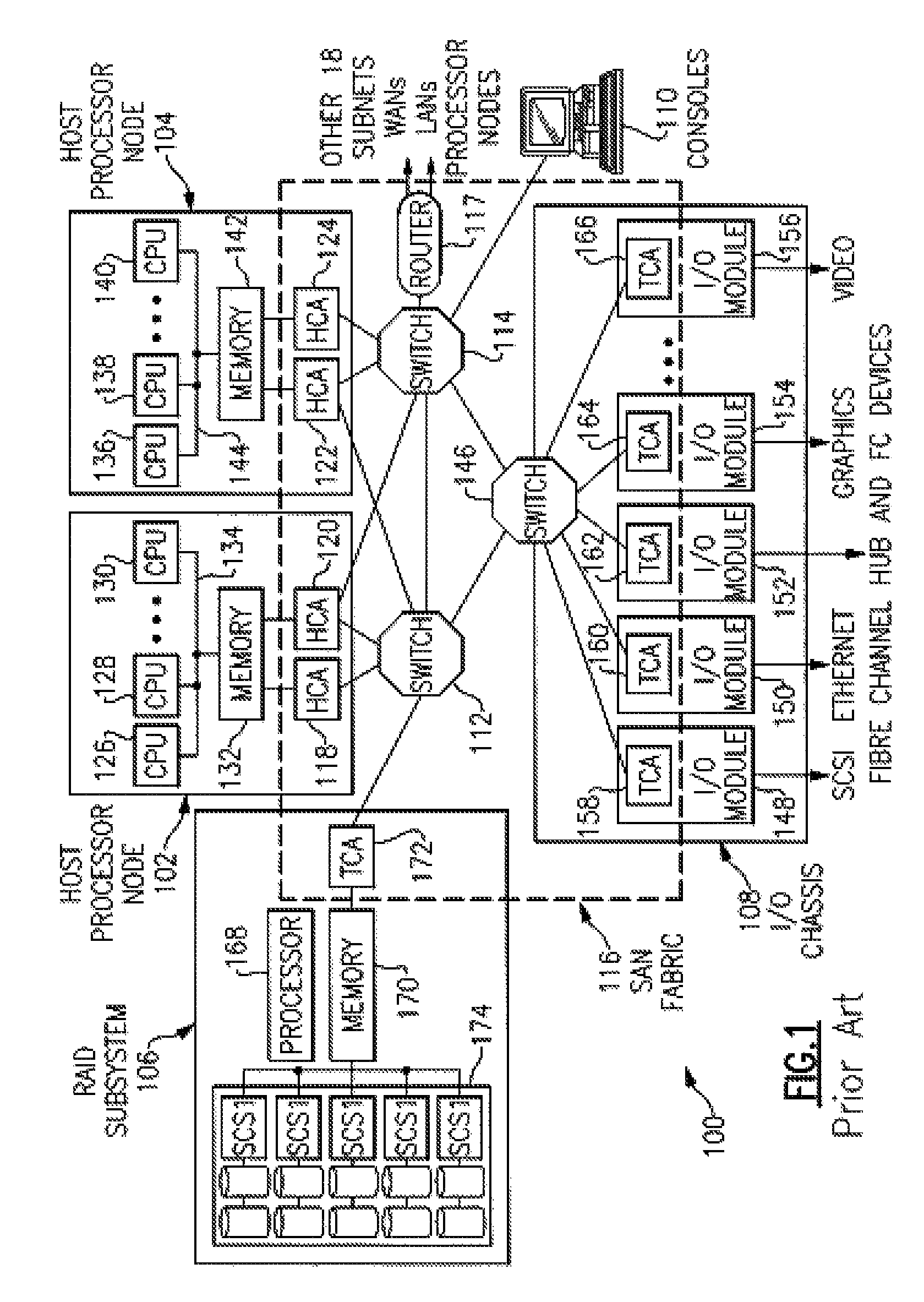
[0029]FIG. 1 is a prior art diagram of a distributed computer system where exemplary embodiments may be implemented. The distributed computer system represented in FIG. 1 takes the form of a System Area Network (SAN) 100 and is provided merely for illustrative purposes. Exemplary embodiments of the present invention described below can be implemented on computer systems of numerous other types and configurations. For example, computer systems implementing the exemplary embodiments can range from a small server with one processor and a few input / output (I / O) adapters to massively parallel supercomputer systems with hundreds or thousands of processors and thousands of I / O adapters.

[0030]Referring to FIG. 1, a SAN 100 is a high-bandwidth, low-latency network for interconnecting nodes within a distributed computer system. A node is any component attached to one or more links of a network and forming the origin and / or destination of messages within the network. In the example depicted in...


PUM


Abstract

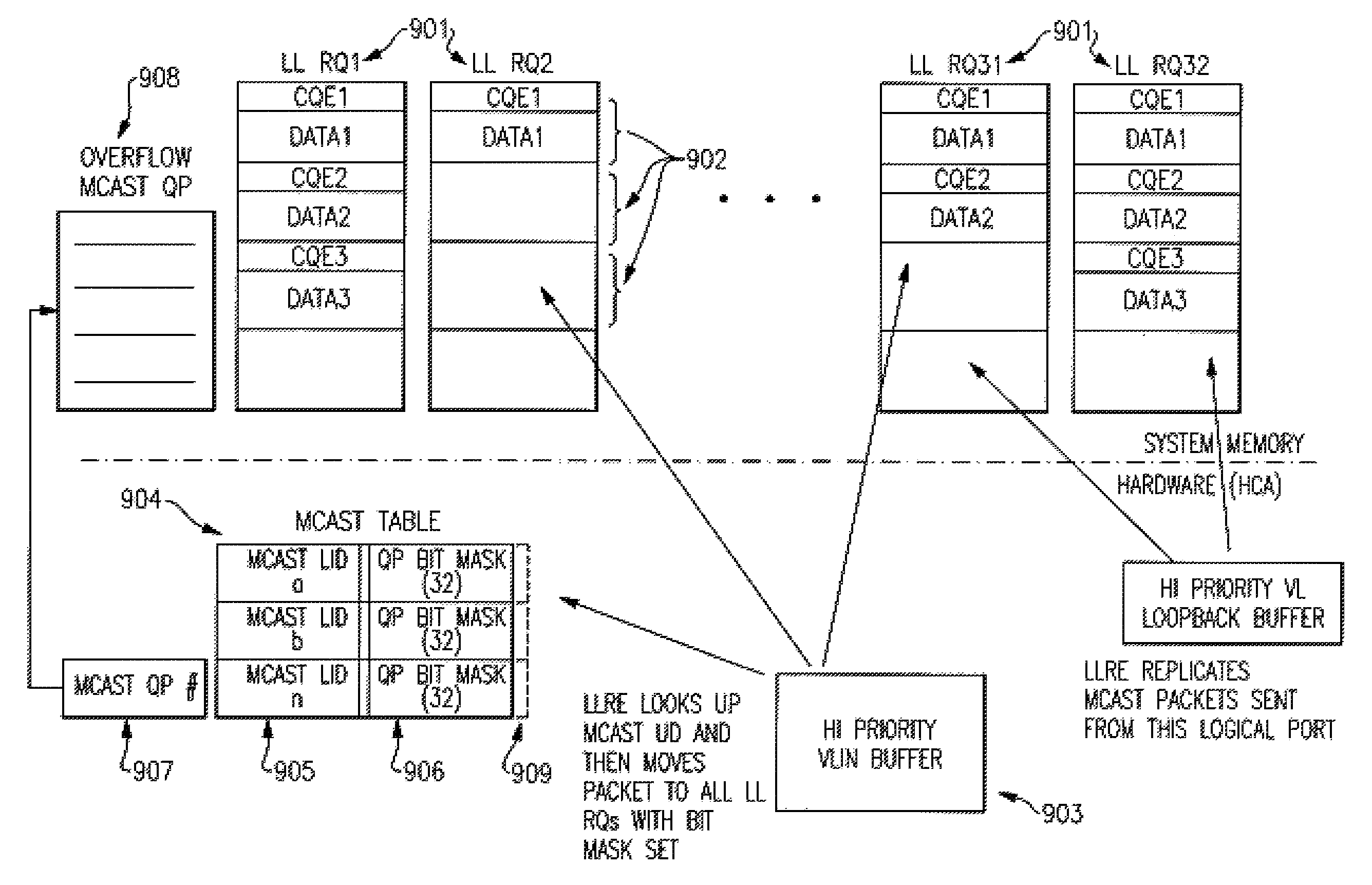
A low latency multicasting receive and send apparatus and method comprising low latency receive and send queues. In an InfiniBand® network each destination group of nodes (recipients) is identified by a unique Global ID (GID)+Local ID (LID). Each node whose ports are part of a multicast group identify themselves via a LID which identifies participating ports. When a switch receives such a multicast packet with a multicast LID in the packet's DLID field it replicates the packet to each of the designated ports. Each destination adapter at a receiving node receives the multicast packet and distributes copies of the packet to QPs in the host system that are registered for the multicast address.

Description

BACKGROUND OF THE INVENTION[0001]1. Technical Field of the Invention[0002]This invention pertains to computer system communication. In particular, this invention provides low latency message reception and replication in an InfiniBand® multicast implementation.[0003]2. Description of the Related Art[0004]I / O adapters define queue pairs (QPs), comprising receive queues (RQ) and send queues (SQ), for conveying messaging information from a software consumer to the adapter prior to transmission over a network fabric and for receiving messages by the consumer from an adapter coupled to the network fabric. Industry standards, such as the InfiniBand® (IB) Architecture Specification available from the InfiniBand® Trade Association and IWarp from the RDMA Consortium, specify that the message information carried on QPs is in the form of a work queue element (WQE) that carries control information pertaining to the message. The above-identified documents are incorporated herein by reference in t...

Claims


Application Information

Patent Timeline
Patent Type & Authority Patents(United States)
IPC IPC(8): H04J1/16H04L12/56
CPCH04L45/16H04L45/60H04L49/201H04L49/35H04L49/358
Inventor CRADDOCK, DAVIDGREGG, THOMAS A.
Owner IBM CORP
Learn More