Low-frequency power line emissions reduction system and method

a technology of low-frequency power lines and emissions reduction, applied in the direction of antennas, electrical equipment, electrical long antennas, etc., can solve the problems of significant low-frequency current emissions that are conducted back out on the power lin

Active Publication Date: 2011-03-01
ROCKWELL COLLINS INC
View PDF23 Cites 11 Cited by
  • Summary
  • Abstract
  • Description
  • Claims
  • Application Information

AI Technical Summary

Benefits of technology

What is provided is a radio system. The radio system comprises a power source and a power amplifier circuit coupled to the power source on a power line. The radio system also comprises an active cancellation circ

Problems solved by technology

Various conventional electronic systems with significant load modulation, such as RF power amplifier applications, may result in significant low-frequency current emissions that are conducted back out on the power line.
Meeting these requirements for low freq

Method used


Image

  • Low-frequency power line emissions reduction system and method
  • Low-frequency power line emissions reduction system and method
  • Low-frequency power line emissions reduction system and method

Examples


Embodiment Construction

Before describing in detail the particular improved system and method, it should be observed that the invention includes, but is not limited to a novel structural combination of conventional data / signal processing components and communications circuits, and not in the particular detailed configurations thereof. Accordingly, the structure, methods, functions, control and arrangement of conventional components and circuits have, for the most part, been illustrated in the drawings by readily understandable block representations and schematic diagrams, in order not to obscure the disclosure with structural details which will be readily apparent to those skilled in the art, having the benefit of the description herein. Further, the invention is not limited to the particular embodiments depicted in the exemplary diagrams, but should be construed in accordance with the language in the claims.

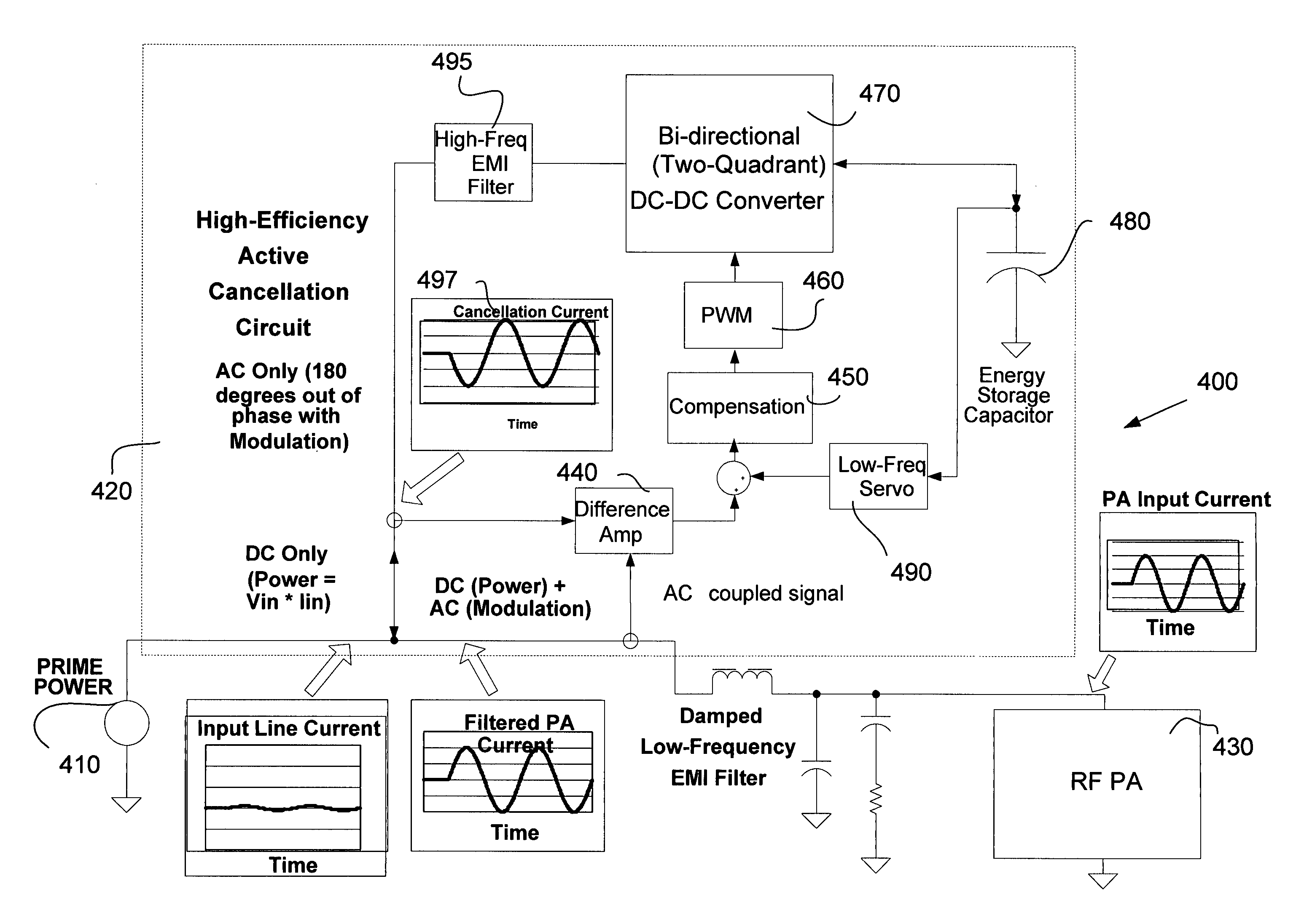
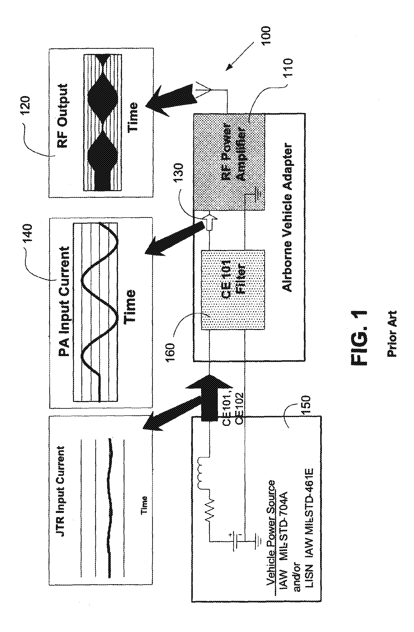
In a variety of RF communication devices and other electronic systems, RF Power Amplifiers (and pos...


PUM


Abstract

A radio system comprises a power source and a power amplifier circuit coupled to the power source on a power line. The radio system also comprises an active cancellation circuit. The active cancellation circuit comprises a bi-directional DC-DC converter. The active cancellation circuit is configured to cancel low-frequency emissions from the power amplifier circuit on the power line.

Description

BACKGROUNDThe invention generally relates to systems and methods which may be applied to communications and other types of electronics systems. In particular the invention relates to systems and methods which provide for filtering of low frequency emissions onto the prime power line for the communications equipment.Various conventional electronic systems with significant load modulation, such as RF power amplifier applications, may result in significant low-frequency current emissions that are conducted back out on the power line. For example, modulation waveforms such as AM voice, ASK AM, Have. Quick IIA, and the like, all may exhibit such emissions. Electromagnetic Interference / Electromagnetic Compatibility (EMI / EMC) standards such as MIL-STD-461 CE101, limit the conducted emissions that an equipment may generate at the power input interface. Meeting these requirements for low frequency emissions, such as for AM voice, requires filters (including large capacitors and inductors) wi...

Claims


Application Information

Patent Timeline
IPC IPC(8): H04B1/04H01Q11/12
CPCH04B15/005
Inventor SCHONEMAN, GEORGE K.SCHONEMAN, LEGAL REPRESENTATIVE, DEBRA S.DUNFORD, BRADLEY J.
Owner ROCKWELL COLLINS INC
Why Eureka
Try Eureka