Electrophoretic display device and electronic apparatus

a display device and display device technology, applied in the field of electrophoretic display devices and electronic devices, can solve the problems of large power consumption of total leakage currents, weak conductivity of adhesive agent layers, and generation of leakage currents between adjacent pixel electrodes, so as to reduce the generation of leakage currents, improve reliability, and reduce power consumption

Inactive Publication Date: 2011-03-08
E INK CORPORATION
View PDF5 Cites 2 Cited by
  • Summary
  • Abstract
  • Description
  • Claims
  • Application Information

AI Technical Summary

Benefits of technology

[0011]An advantage of some aspects of the invention is that it provides an electrophoretic display device capable of implementing low-power consumed driving by suppressing a leakage current between pixels and improving reliability. In addition, it also provides an electronic apparatus having the above-described electrophoretic display device.
[0014]According to the above-described electrophoretic display device, the electric field that extends from the pixel electrode at the time of applying a voltage arrives at the floating electrode disposed between the pixel electrodes at once and then extends from the floating electrode again. Then, compared to a case where the floating electrode is not disposed, an increase of the electric field to the common electrode side is prioritized, and accordingly, the electric field between the pixel electrodes decreases. Since the electric field that causes flow of electrons between the pixel electrodes decreases, generation of the leakage current between the pixel electrodes is suppressed, and thereby an electrophoretic display device implementing low power consumption can be configured.
[0016]In such a case, for example, compared to a case where the floating electrode is disposed along one side of the pixel electrode, generation of the leakage current between adjacent pixels can be suppressed more assuredly. In particular, generation of a leakage current between adjacent pixel electrodes that are disposed on an extended line of a diagonal line of the pixel electrodes can be suppressed further.
[0020]In such a case, generation of the leakage current can be suppressed more assuredly. In addition, the electric potential of the floating electrode can be stabilized at an intermediate electric potential between two pixels positioned on both sides of the floating electrode. Furthermore, the influence of capacitive combination of various driving elements, various wirings, and the like that are disposed on a lower layer of the floating electrode can be distributed.
[0022]In such a case, the pixel electrode and the floating electrode can be formed separately by performing delicate processing for a thin film of a same formation material. Accordingly, even when high definition is implemented in the device, the floating electrode can be formed well, and thereby an electrophoretic display device implementing low power consumption can be configured.
[0028]According to the above-described electronic apparatus, an electronic apparatus that suppresses generation of the leakage current between pixels so as to implement low power consumption and improves the reliability thereof can be configured.

Problems solved by technology

Thus, the adhesive agent layer may sometimes have weak conductivity due to the impurities.
In such a case, when the pixel electrodes are connected through the above-described adhesive agent layer having weak conductivity, a leakage current is generated between the adjacent pixel electrodes due to the electric potential difference between the pixel electrodes.
However, when the leakage currents are generated in a plurality of spots, the total leakage currents consume large power.
For example, when there are many spots in which different colors are displayed in adjacent pixels, as described above, that is, when complicated display is performed, the power consumption increases, and thereby driving at low power consumption, which is one of the advantages of the electrophoretic display device, cannot be performed.
Accordingly, the electrophoretic particles cannot be easily migrated based on the design thereof, and defective display such as display of a gray color that is in the middle of a black color and a white color can easily occur.
Therefore, the display quality is degraded.
In addition, the pixel electrode may incur a chemical reaction due to generation of the leakage current.
Accordingly, when used for a long time, the pixel electrode deteriorates, and accordingly, display cannot be performed well.
Furthermore, the reliability of the electrophoretic display device may be lowered.

Method used


Image

  • Electrophoretic display device and electronic apparatus
  • Electrophoretic display device and electronic apparatus
  • Electrophoretic display device and electronic apparatus

Examples


first embodiment

[0037]Hereinafter, an electrophoretic display device according to a first embodiment of the invention will be described with reference to FIGS. 1A to 5C. In all the drawings described below, for easy understanding of the drawings, the scales of the film thicknesses and dimensions of constituent elements are differently set appropriately.

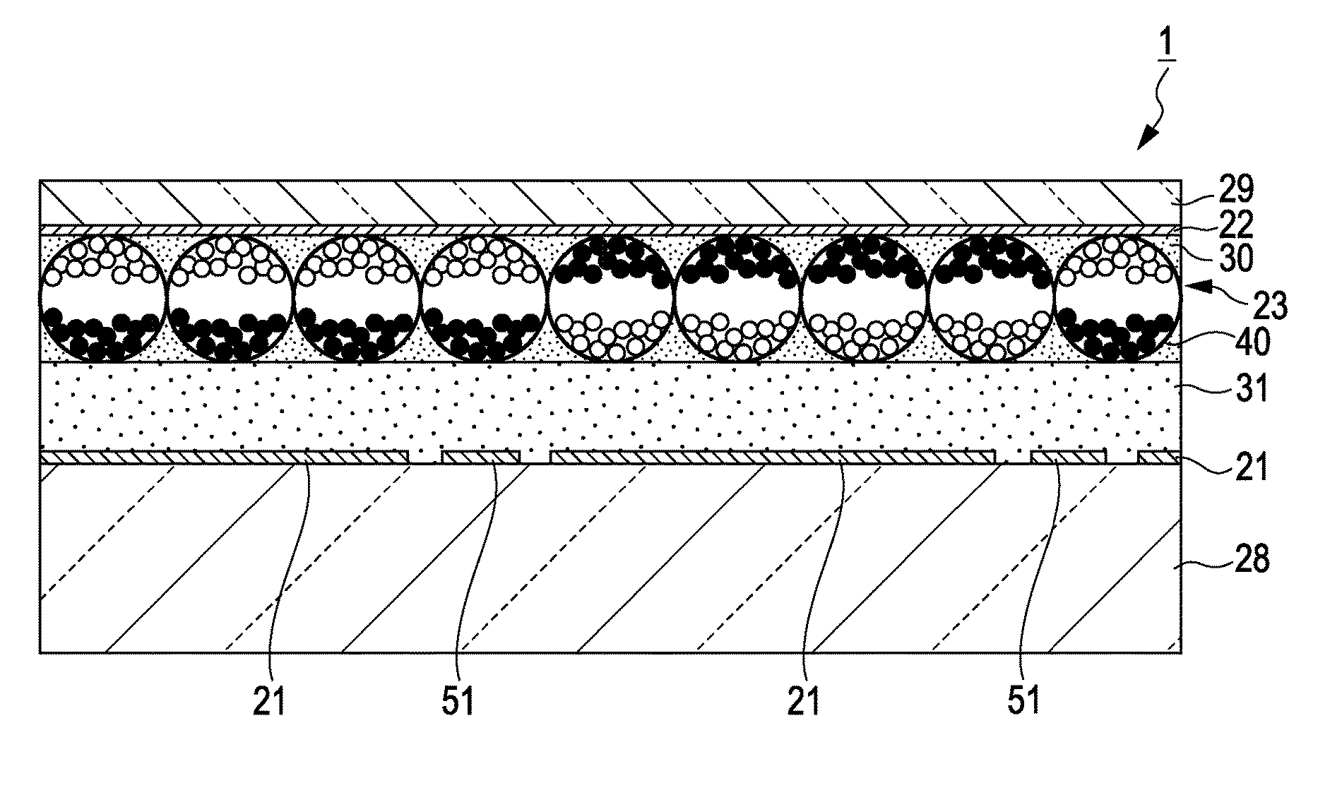
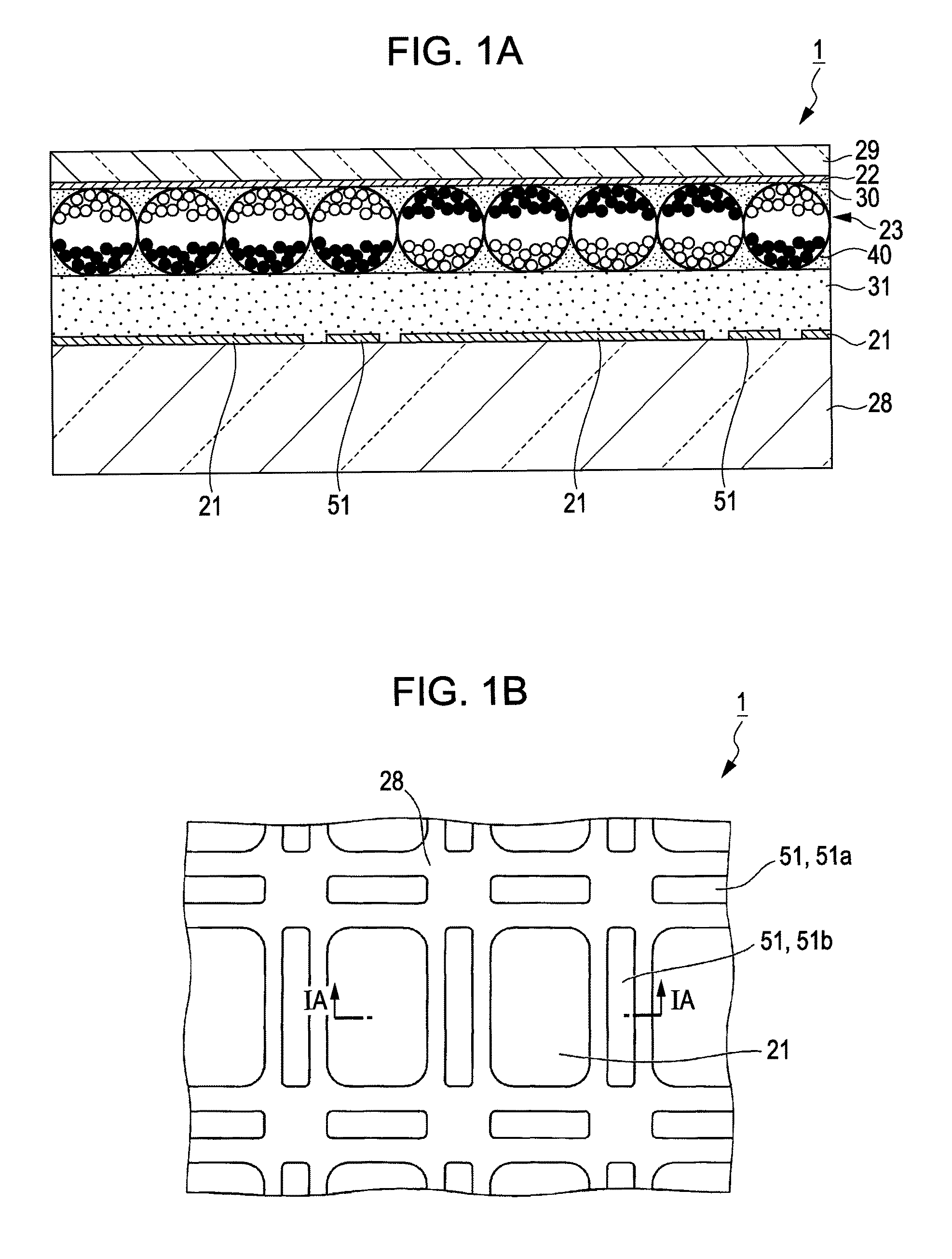
[0038]FIGS. 1A and 1B are explanatory diagrams of an electrophoretic display device 1 according to this embodiment. FIG. 1A is a cross-section view of the electrophoretic display device 1, and FIG. 1B is a plan view of the electrophoretic display device 1. FIG. 1A is a cross-section view taken along line IA-IA shown in FIG. 1B.

[0039]As shown in FIG. 1A, the electrophoretic display device 1 according to this embodiment includes a component substrate (first substrate) 28 that has a plurality of pixel electrodes 21, an opposing substrate (second substrate) 29 that has a common electrode 22, and an electrophoretic element layer 23 that is sandwiched by b...

modified examples

[0075]Based on the purpose of the invention of suppressing the leakage current by disposing the intermediate electric potential electrode between adjacent pixel electrodes so as to change the propagation pattern of the electric field (lines of electric force), it is apparent that the shape or the disposition of the intermediate electric potential electrode can be changed. Hereinafter, the shape and the disposition of the intermediate electric potential electrode according to several modified examples will be described. FIGS. 5A to 5C are plan views of the modified examples and are diagrams corresponding to FIG. 1B.

[0076]In FIG. 5A, the intermediate electric potential electrodes 52a extend up to intersections of pixel electrodes 21 that are disposed vertically and horizontally in a lattice shape in the plan view. In other words, the intermediate electric potential electrode 52a that is disposed along the short side of the pixel electrode 21 extends along an extended line of the short...

second embodiment

[0080]FIGS. 6A and 6B are explanatory diagrams of an electrophoretic display device according to a second embodiment of the invention. FIG. 6A is a cross-section view of the electrophoretic display device, and FIG. 6B is a plan view of electrophoretic display device. FIG. 6A shows a cross-section view taken along line VIA-VIA shown in FIG. 6B.

[0081]The electrophoretic display device according to this embodiment is common to a part of that according to the first embodiment. A difference between the first embodiment and the second embodiment is that an insulation layer 60 that covers the intermediate electric potential electrodes 51 and protrudes to the electrophoretic element layer 23 side relative to upper faces of the pixel electrodes 21 is formed in the second embodiment. Thus, to each constituent element of the second embodiment that is common to the first embodiment, a same reference sign is assigned, and a detailed description thereof is omitted here.

[0082]As shown in FIG. 6A, ...


PUM

PropertyMeasurementUnit
electric potentialaaaaaaaaaa
particle diameteraaaaaaaaaa
thicknessaaaaaaaaaa

Abstract

An electrophoretic display device includes a first substrate on which a pixel electrode and another pixel electrode that is adjacent to the pixel electrode are formed, a second substrate on which a common electrode facing the pixel electrode and the another pixel electrode that is adjacent to the pixel electrode is formed, a plurality of electrophoretic elements that is sandwiched by the first substrate and the second substrate and has charged electrophoretic particles, and an adhesive agent layer that is disposed between the plurality of electrophoretic elements and the first substrate. A floating electrode that is electrically isolated is disposed between the pixel electrode and the another pixel electrode that is adjacent to the pixel electrode on the first substrate.

Description

BACKGROUND[0001]1. Technical Field[0002]The present invention relates to an electrophoretic display device and an electronic apparatus.[0003]2. Related Art[0004]As one type of display devices, there are electrophoretic display devices that perform display by migrating charged particles (electrophoretic particles) that are dispersed in a dispersion medium in accordance with an electric field that is generated between electrodes and controlling the distribution state of the charged particles. Generally, the above-described electrophoretic display devices have structural advantages that the electrophoretic display devices do not need a light source such as a front light due to high reflectivity of the electrophoretic particles and can be formed to be thin and quality advantages that the viewing angle is wide and the contrast is high. In addition, since any back light is not needed, the electrophoretic display devices have an advantage that low power consumption can be implemented, as w...

Claims


Application Information

Patent Timeline
Patent Type & Authority Patents(United States)
IPC IPC(8): G02B26/00G02F1/167G02F1/16756G02F1/16761
CPCG02F1/167G02F2001/1672G02F2001/1676G02F2202/28G02F1/1681G02F1/16761G02F1/16756G02F1/1676
Inventor ABEKOSHIHARA, TAKESHI
Owner E INK CORPORATION
Why Eureka
Try Eureka