
Part washer

a washer and part technology, applied in the field of parts washers, can solve the problems of reducing the whole cleaning efficiency and delay in the whole working process of repairing and conserving parts, and achieve the effects of increasing the cleaning efficiency, enhancing the discharge pressure, and increasing the cleaning and drying efficiency

Inactive Publication Date: 2011-03-15
KIM SUNG IL
View PDF17 Cites 6 Cited by
  • Summary
  • Abstract
  • Description
  • Claims
  • Application Information

AI Technical Summary

Benefits of technology

"The present invention is a part washer that improves the efficiency of cleansing and drying parts using a high-pressure air injection means. The washer includes a heating device that heats the air and cleansing solution before it is sprayed onto the parts. This improves the efficiency of the cleaning process compared to conventional devices that use a separate drying device. The washer is also economical because it uses the same heating device for both cleaning and drying. Additionally, the washer can improve heating efficiency during the winter season by heating the air and solution simultaneously."

Problems solved by technology

However, in case of such a general part washer having a simple function of discharging the cleansing solution, there is produced a problem that whole cleansing efficiency has been reduced because the temperature of the cleansing solution is lowered to thereby decrease the cleansing force of the cleansing solution at the cold winter season, and the cleansing solution is sprayed at such state.
However, in such conventional part washer, since there has not provided a separate drying device for drying the cleansing solution stained to the parts to be cleansed after the completion of the cleansing works, it is necessary for the users to clean the cleansing solution with a towel and the like or to dry it naturally.
As a result, there is produced a problem that whole working process for repairing and conserving the parts is delayed because drying work takes long time.

Method used

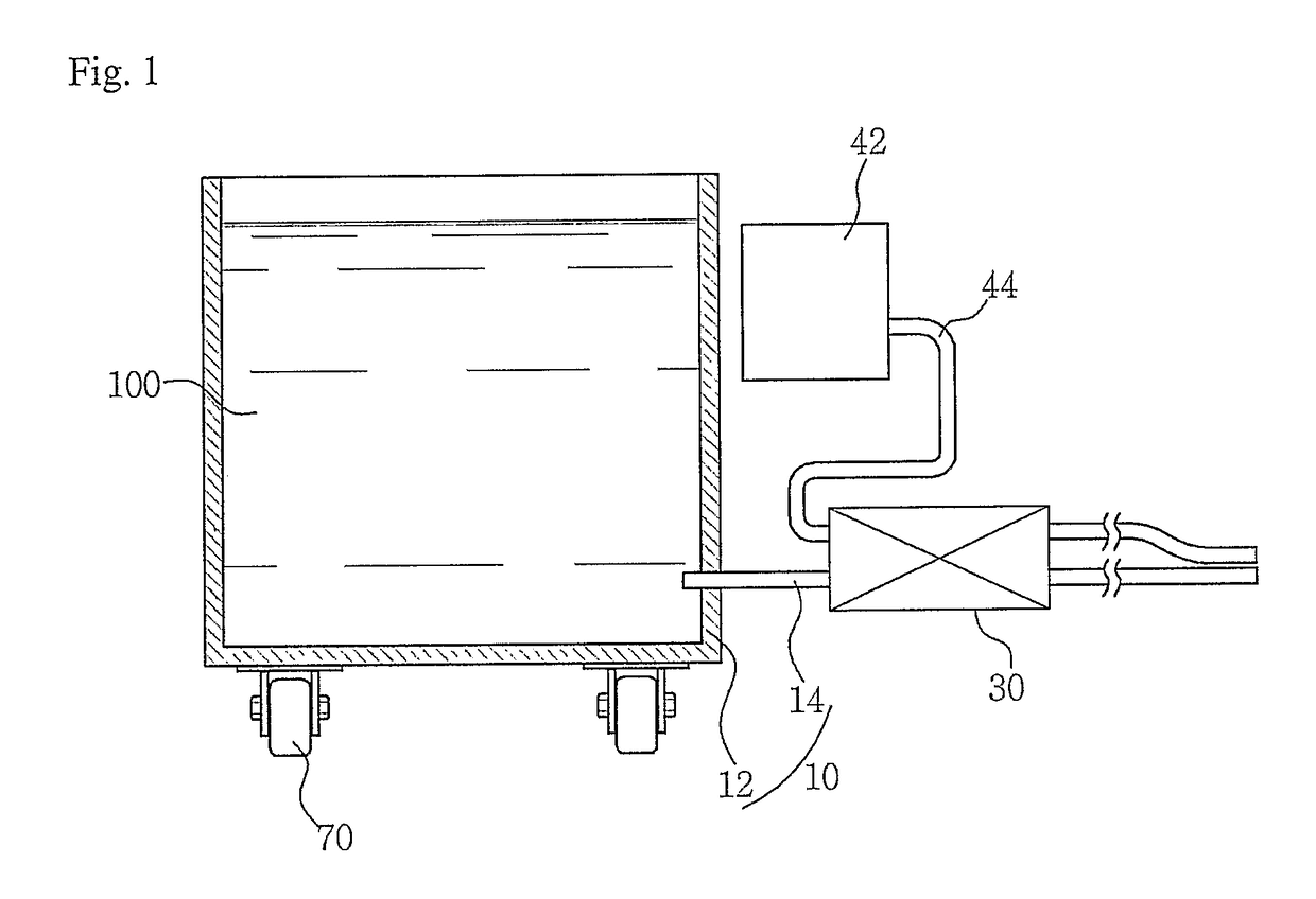
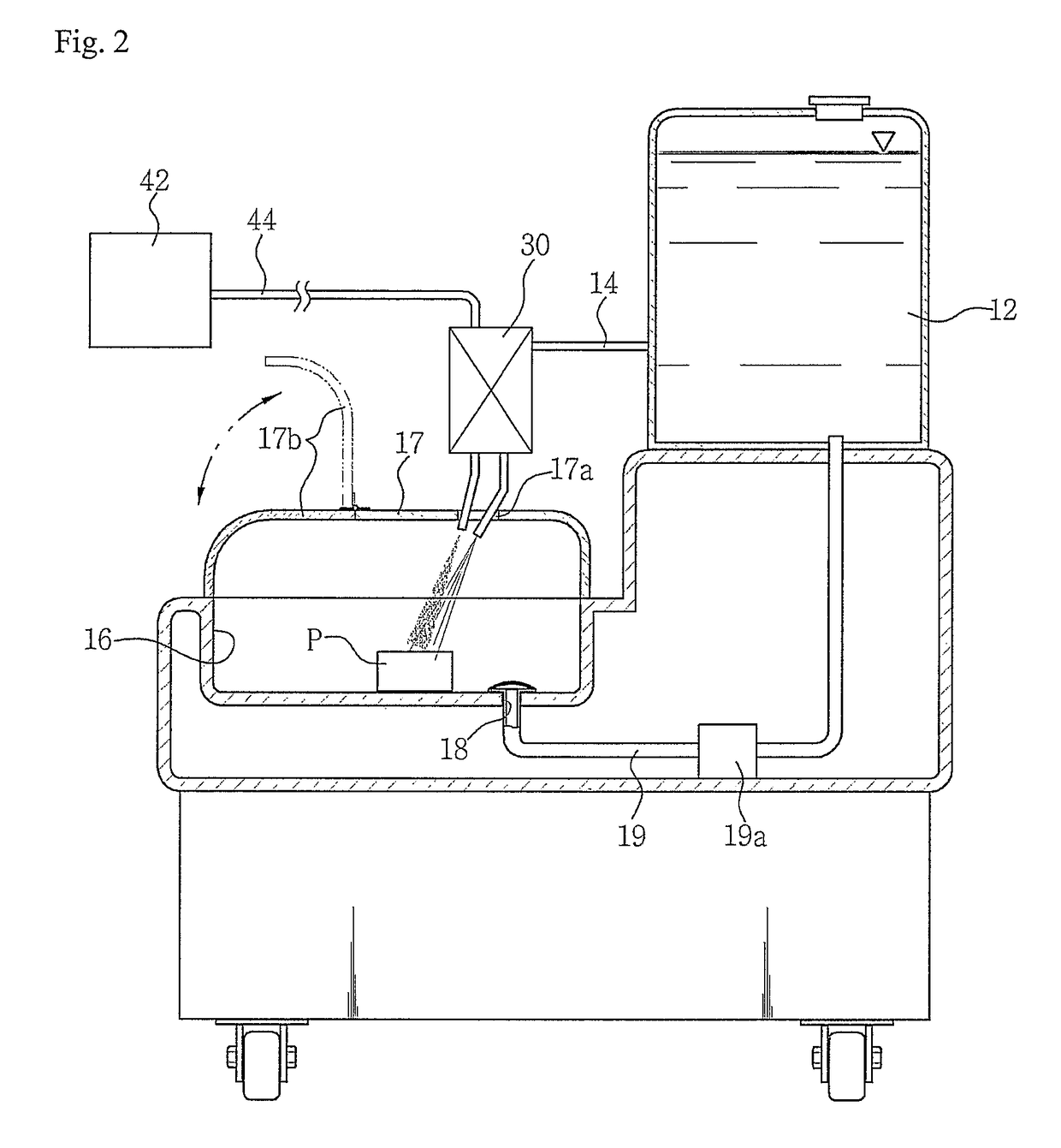
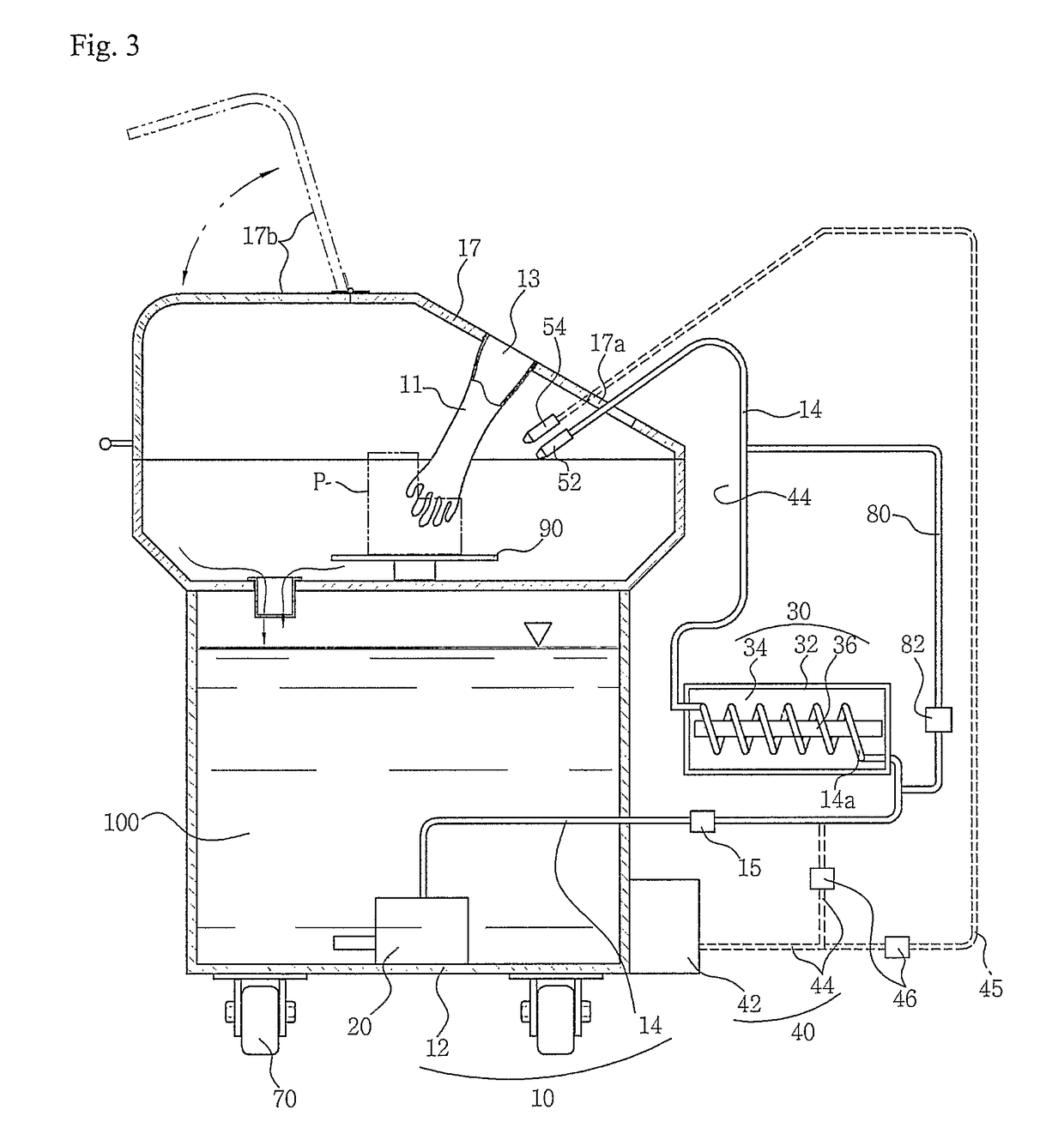

Image

  • Part washer
  • Part washer
  • Part washer

Examples


Embodiment Construction

To accomplish the above objects, the part washer of the present invention basically comprises:

cleansing means for cleansing parts to be cleansed by discharging the cleansing solution to the outside, and

heating means for heating the cleansing solution before it is discharged to the parts so that the cleansing solution can be discharged at the heated state.

Further, according to the present invention, air injection means is also installed for emitting the high-pressure air into the outside in order to enhance the discharge pressure of the cleansing solution or to dry the cleansing solution stained on the parts, so that the high-pressure air injected from the air injection means as well as the cleansing solution can be heated by the heating means.

Hereinafter, the part washer of the present invention will be described in detail with reference to the appended drawings. In the drawings, the same reference numerals are used to designate the same or similar components through all the drawing...


PUM


Abstract

An apparatus for cleaning an article comprises: a solution receptacle (12) for storing cleaning solution (100); a cleaning chamber (16) for receiving an article (P) to clean; a material transporting conduit including a solution conduit (14) connected between the solution receptacle and the cleaning chamber for transporting the cleaning solution from the solution receptacle to the cleaning chamber to apply to the article received in the cleaning chamber, the material transporting conduit further including an air conduit (44) connected to a high-pressure air source (42) for transporting the high-pressure air there-through and to apply to the article; and a heating device (30) coupled with the solution conduit (14) and the air conduit (44) for heating both the cleaning solution in the solution conduit and the high-pressure air in the air conduit concurrently and to a heated temperature prior to applying to the article.

Description

TECHNICAL FIELDThe present invention relates to a part washer for washing various parts using a cleansing solution, in particular to a part washer, which discharges the high-pressure air to be injected to the parts and the solution for cleansing the parts at the state where they are heated by means of heating means, and heats the high-pressure air moving at high velocity smoothly, thereby improving cleansing and drying efficiencies in comparison with a conventional art.BACKGROUND ARTIn general, a part washer is employed for cleansing various machinery parts used in a repair shop or in the several industrious field. Such a separate part washer is used in cleansing oil dusts and the like stained to the parts in the process of repairing and maintaining the machine. In operating such a conventional part washer, cleansing solution accommodated in a drum is at first discharged via a pump, and the parts are cleaned by using the cleansing solution. In this instance, users conventionally hav...

Claims


Application Information

Patent Timeline
Patent Type & Authority Patents(United States)
IPC IPC(8): B08B3/02
CPCB05B7/1646B08B3/006B08B3/02B08B15/026F28D15/00B01F5/0413B01F25/312
Inventor KIM, SUNG-IL
Owner KIM SUNG IL
Learn More