Expanding, exposed-blade arrow head

a technology of exposed blades and arrow heads, applied in the field of arrow heads, can solve the problems of reducing and reducing the cutting radius so as to reduce the aerodynamic impact probability, reduce the profile, and increase the cutting diameter of the arrow head

Inactive Publication Date: 2011-03-15
ERHARD RORY J
View PDF22 Cites 35 Cited by
  • Summary
  • Abstract
  • Description
  • Claims
  • Application Information

AI Technical Summary

Benefits of technology

[0014]The purpose of the invention is to provide an expandable arrow head that incorporates the best features of both types of broadheads into one product. To the archer, the invention provides the security of having exposed blades with the desired larger cutting diameter of mechanical broadheads. In flight, the blades have a low profile, so there is a much lower probability that aerodynamics will affect the flight path. Upon impact, the blades expand laterally, thereby increasing the cutting diameter of the arrow head. Moreover, penetrating kinetic energy is not decreased when the blades expand.
[0016]When the arrow hits its target, the force that the target applies to the tip of the arrow head causes the kinetic energy of the moving arrow to push the forcing cone forward relative to the tip. As the forcing cone moves forward, the angled surface of the forcing cone forces the rear ends of the blades to expand laterally, increasing the cutting diameter of the broadhead. Upon impact, the target's resistance force pushing backward on the tip is greater than the compression force of the spring, which maintains the larger cutting diameter while the broadhead passes through the target. The increased cutting diameter gives the hunter a quicker, humane kill. In an alternative embodiment, an expansion spring is used and bottom end of the tip expands the spring as the tip moves into the ferrule cavity.
[0017]In another preferred embodiment, a shear pin and not a spring prevents the rearward movement of the tip and expansion of the blades during flight. When the tip hits the target, a piston that is forms the rear end of the tip cuts the shear pin, allowing the blades to expand. In this embodiment, a spring is not required. Any shearable structure may be substituted for the shear pin. Alternatively, a crushable structure that is situated in the ferrule cavity may also be relied upon.

Problems solved by technology

This action consumes vital kinetic energy, forcing the blades in a counter productive direction until the blades rotate over center.
The hunting regulations of some states prohibit the use of mechanical broadheads because they may not open correctly and ensure a humane kill.
When they hit a heavy bone, however, they bend, fold, or dull.
Common problems associated with these two types of background art broadheads have consumer sentiment split about which type works best.
Conversely, fixed blades are usually considered less accurate because the exposed blades are influenced by the air as it passes through them, causing the arrow to hit a different spot than the archer's field point.
Moreover, the probability that a mechanical broadhead will not open at all or will not open to full cutting diameter is low.
One of the problems with these large-cutting-diameter mechanical broadheads is that the action of the blades folding open consumes a large percentage of the initial energy of the arrow.
This may rob enough kinetic energy from the arrow to prevent a humane kill.
Another limitation is the need to hold the blades in the retracted position with a band, e.g., a rubber band, that must be replaced between uses.
Moreover, none of the background art references disclose a mechanical broadhead that comprises a plunger to which each of its blades is pivotably attached that is longitudinally movable relative to a ferrule having blade holders to which each of its blades is slidably attached, thereby securing said plunger to said ferrule.
Also, none of the background art references disclose a mechanical broadhead that relies on a longitudinally compressible or expandable spring or a shearable or crushable structure to maintain its blades in a retracted position during flight.

Method used


Image

  • Expanding, exposed-blade arrow head
  • Expanding, exposed-blade arrow head
  • Expanding, exposed-blade arrow head

Examples


Embodiment Construction

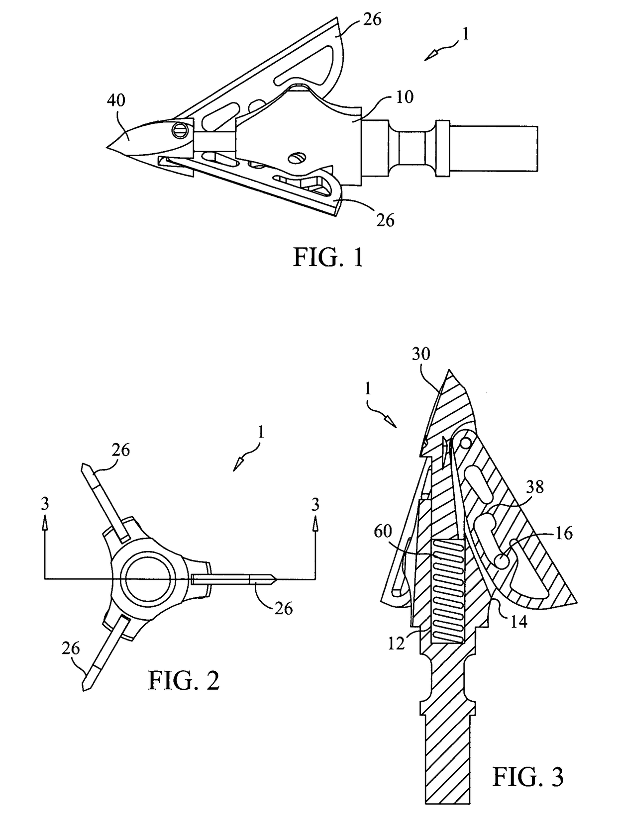
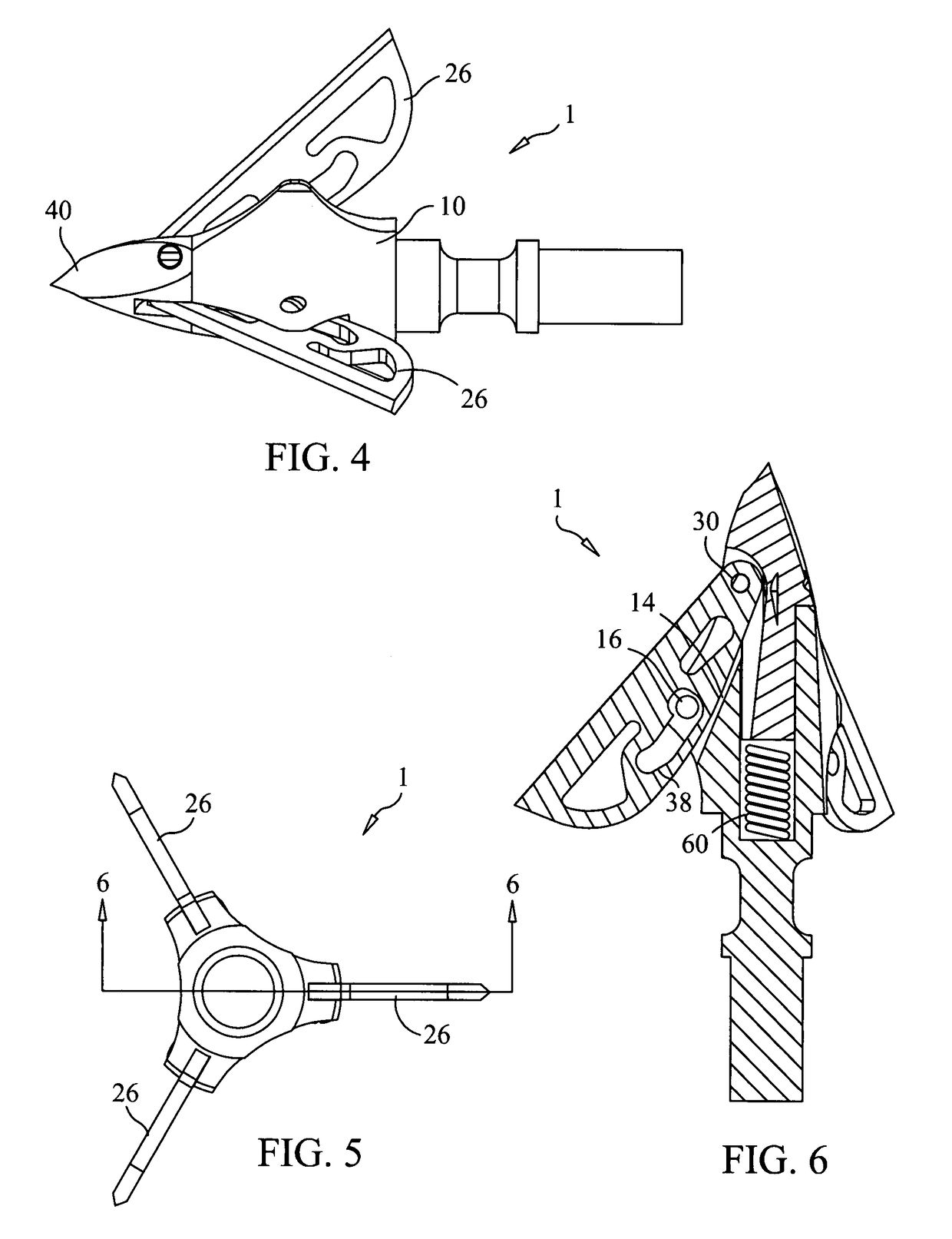
[0068]Referring to FIGS. 1-17, a preferred embodiment the present invention is illustrated in the form of expanding, exposed-blade broadhead 1. Broadhead 1 preferably comprises ferrule 10 and a plurality of cutting blades 26 that are pivotally coupled to tip 40. In use, broadhead 1 is preferably attached to arrow 3.

[0069]Referring to FIGS. 1-3, broadhead 1 is shown in the retracted (initial) position with cutting blades 26 disposed at their smallest cutting diameter. In this position, piston 45 effectively does not compress spring 60 in cavity 12 and screw or pin 16 is disposed at the bottom of slot 38.

[0070]Referring to FIGS. 4-6, broadhead 1 is shown in the extended (final) position with cutting blades 26 disposed at their largest cutting diameter. In this position, piston 45 compresses spring 60 in cavity 12 and screw or pin 16 is disposed at the top of slot 38.

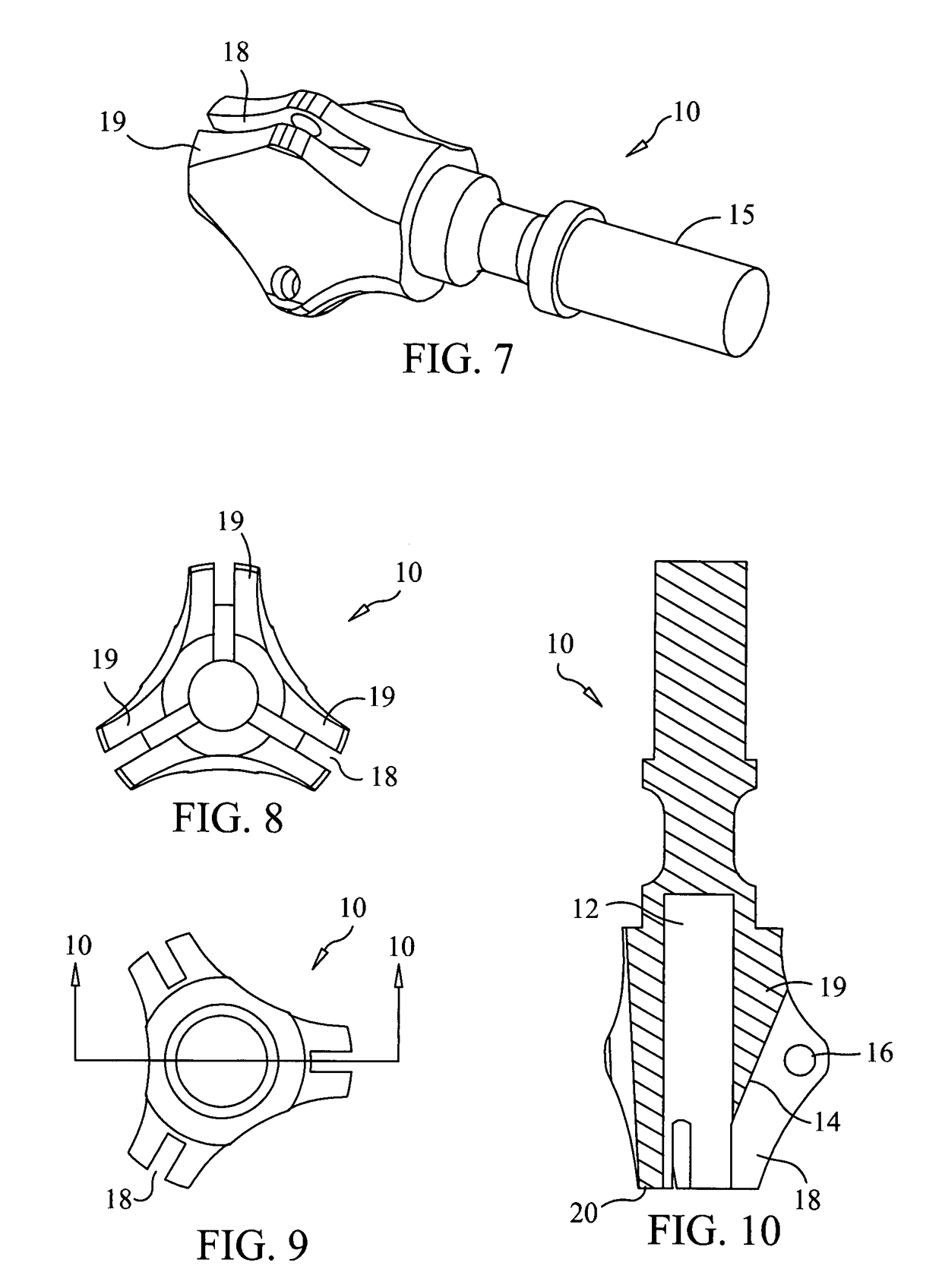
[0071]Referring to FIGS. 7-10, ferrule 10 is shown to preferably have a single spring cavity 12 and a plurality of blade...


PUM


Abstract

An expanding, exposed-blade arrow head and a method of its operation. In a preferred embodiment, the arrow head comprises: a ferrule comprising three blade holders and having a longitudinal cavity having a bottom; a tip comprising a piston that is slidably mounted in the longitudinal cavity, the tip having a front end having three slots; three blades, each of the blades having a forward end that is pivotably mounted in one of said slots and a body having a cutting edge, each body being slidably mounted in one of the blade holders; wherein the sliding of the piston in the longitudinal cavity toward the bottom causes the cutting edges to move outward.

Description

CROSS-REFERENCE TO RELATED APPLICATIONS[0001]This application claims the benefit of U.S. Provisional Patent Application No. 60 / 856,076, filed Nov. 1, 2006, the disclosure of which patent application is incorporated by reference as if fully set forth herein.STATEMENT REGARDING FEDERALLY SPONSORED RESEARCH OR DEVELOPMENT[0002]Not ApplicableINCORPORATION-BY-REFERENCE OF MATERIAL SUBMITTED ON A COMPACT DISC[0003]Not ApplicableBACKGROUND OF THE INVENTION[0004]This invention relates to an arrow head commonly referred to as a broadhead. In particular, the invention relates to expanding, exposed-blade arrow heads.[0005]Currently, there are two common types of broadheads on the market: fixed blade and mechanical. Both have their advantages and disadvantages.[0006]Fixed blades have the cutting blades exposed and mounted so they maintain their position when passing through the target. This type of broadhead usually has a cutting diameter in the range from 0.875 to 1.500 inches. This cutting di...

Claims


Application Information

Patent Timeline
Patent Type & Authority Patents(United States)
IPC IPC(8): F42B6/08
CPCF42B6/08
Inventor ERHARD, RORY J.
Owner ERHARD RORY J
Why Eureka
Try Eureka