
Method and apparatus for charging electric devices

a technology for electric devices and charging devices, applied in special data processing applications, position/direction control, gas pressure propulsion mounting, etc., can solve the problems of inefficient, large energy consumption of continuous electrified rails, and heavy battery weight of vehicles that must be carried in vehicles, and achieve quick and efficient charging and longer time

Inactive Publication Date: 2011-03-15
WFK & ASSOC
View PDF7 Cites 12 Cited by
  • Summary
  • Abstract
  • Description
  • Claims
  • Application Information

AI Technical Summary

Benefits of technology

"This patent describes an electric vehicle that can be powered from discrete and discontinuous electrical contacts embedded along a roadway. The vehicle has a bank of high capacity high voltage capacitors to quickly and efficiently charge its batteries. It also has two charge carrying / storing devices, one capable of receiving a charge quickly and the other requiring a longer time to charge. The vehicle has a rapidly charging battery or capacitor that is secondary to a larger energy storage source. These features make the electric vehicle more efficient and reliable."

Problems solved by technology

Although each of the referenced inventions achieves its own unique objective, all suffer from common drawbacks.
One of these drawbacks concerns the weight of the batteries that must be carried in the vehicle.
Another problem concerns the ability to quickly and efficiently charge the vehicle so as to avoid delays and / or sluggish vehicle response.
Yet, another problem associated with electric powered vehicles is the cost of providing a continuous set of electrified rails along every foot of the roadway.
Continuous electrified rails consume large amounts of energy and are inefficient.
Moreover, the use of a continuous electrical contact rail is problematic because the vehicle can operate for only as long as it has contact with the electrified roadway.
Finally, the electrical contact between the vehicle and rail in the background art is typically a brush that wears out over time or otherwise becomes a source of lost efficiency.

Method used


Image

  • Method and apparatus for charging electric devices
  • Method and apparatus for charging electric devices
  • Method and apparatus for charging electric devices

Examples


Embodiment Construction

[0020]The present invention relates to a method and apparatus for charging electrically powered devices. In accordance with the invention, the device is powered by two storage or charge receiving devices. One of these devices is capable of receiving a substantial charge very rapidly while the other device requires a longer time to receive a charge. The advantage is that the powered device can be used almost instantly and continually while at the same time rebuilding electrical charge.

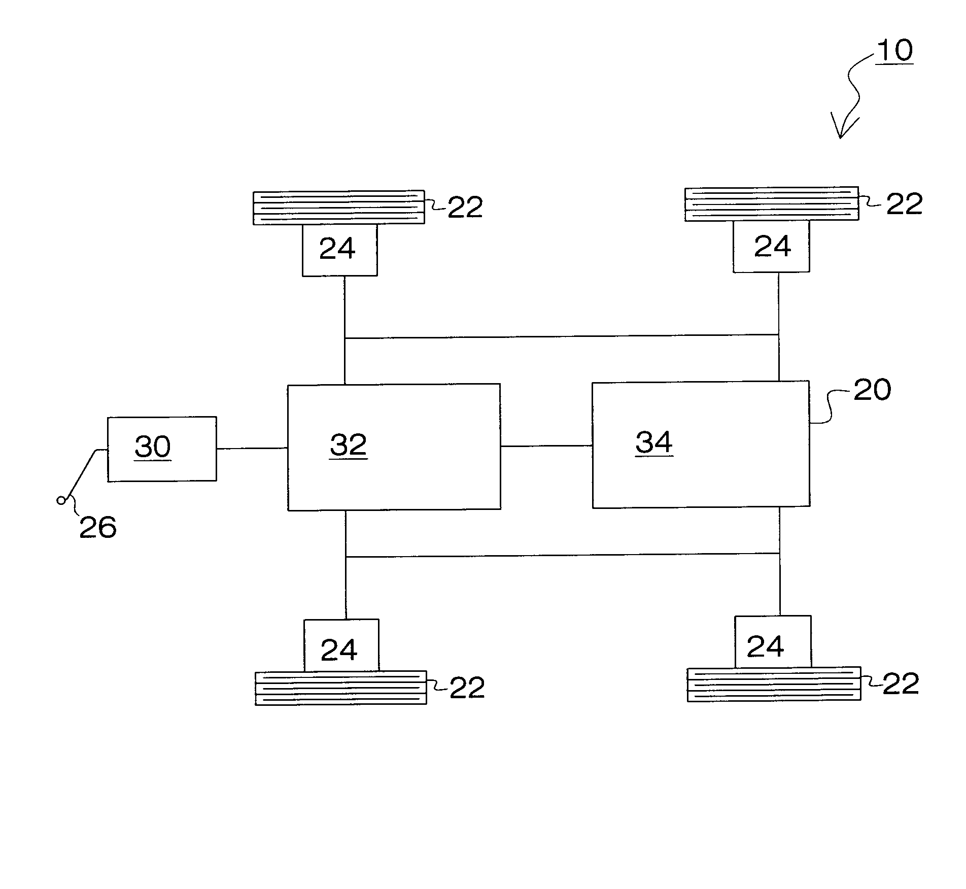
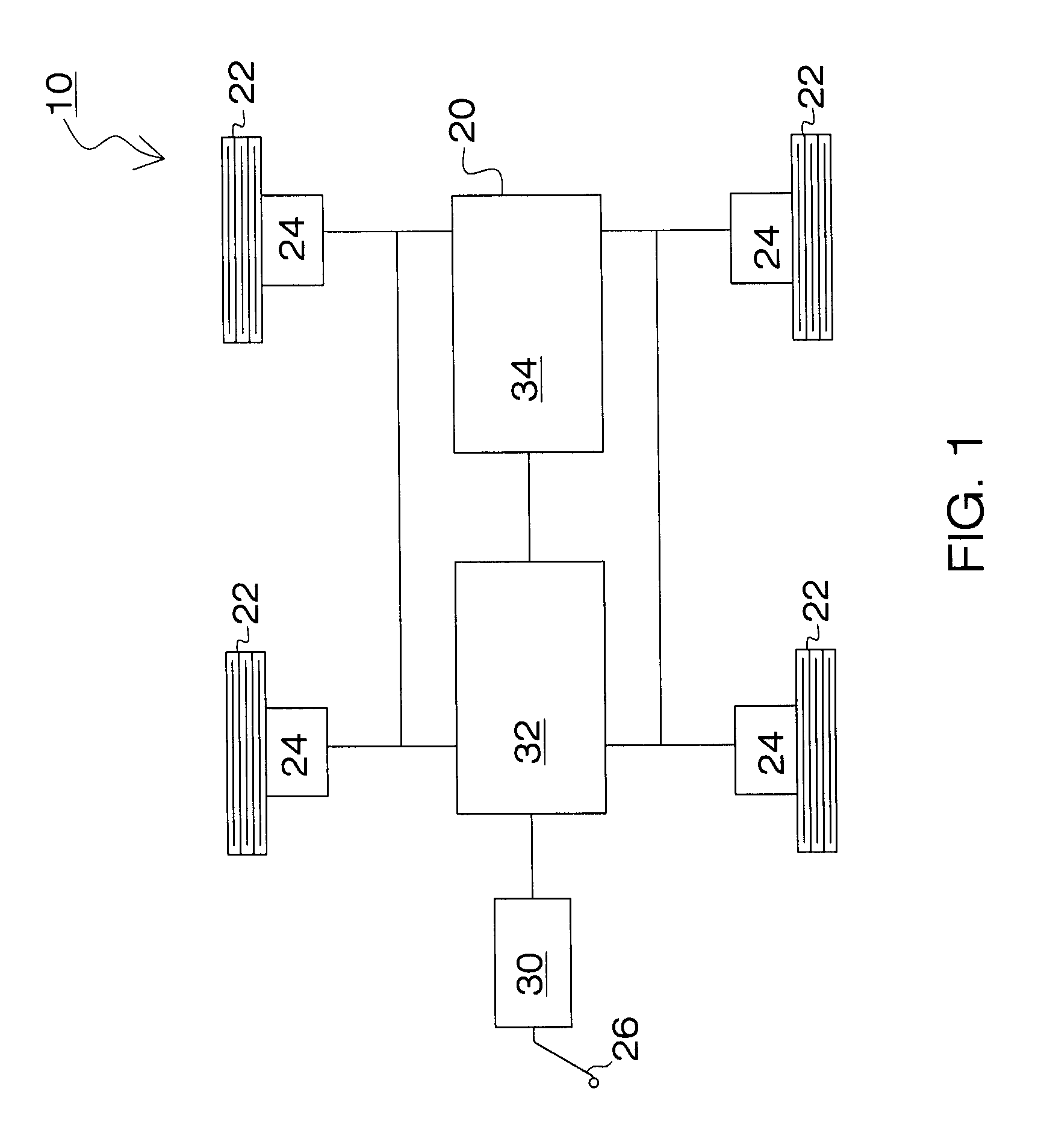
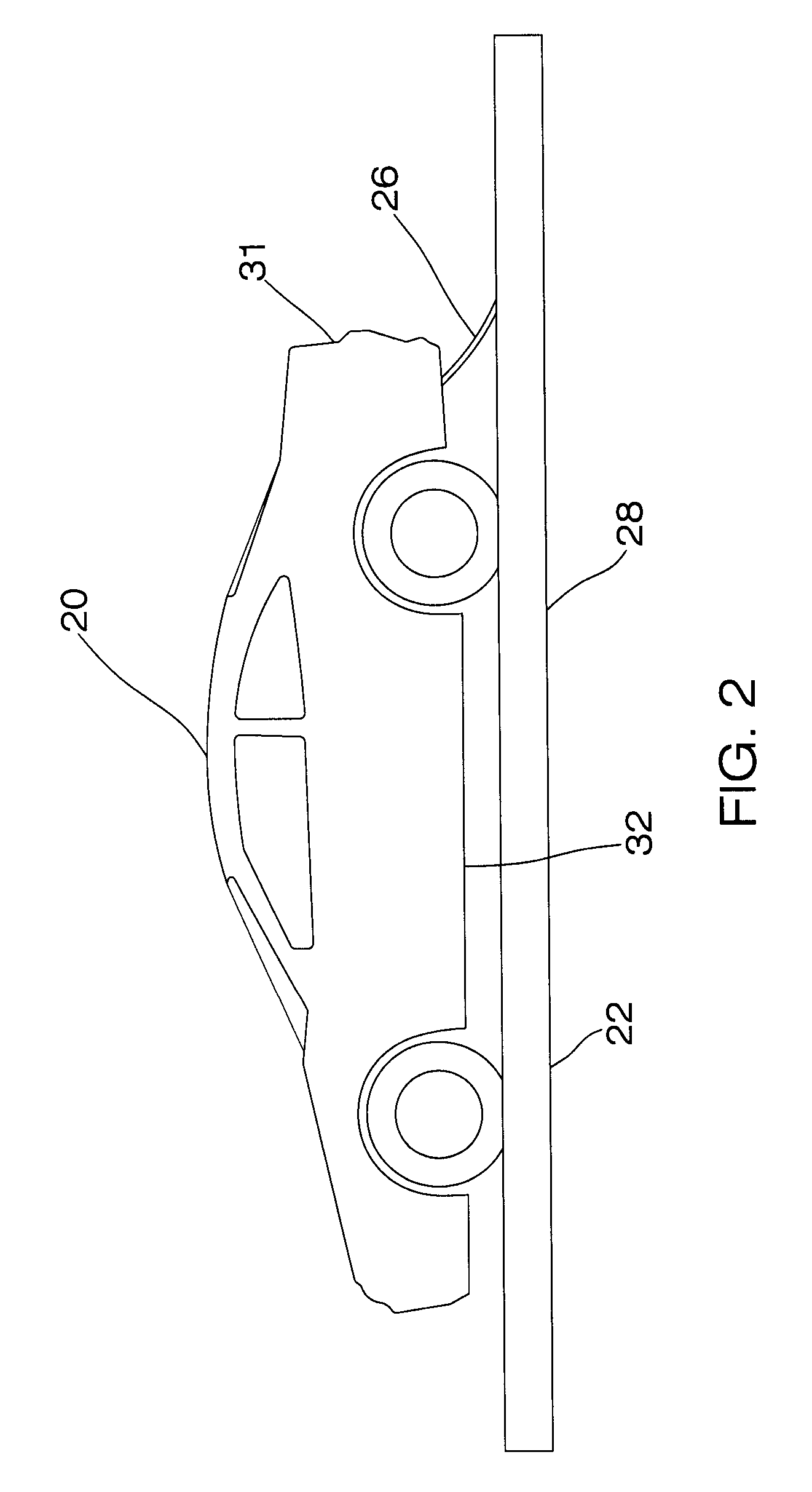
[0021]FIG. 1 is a schematic diagram illustrating the various components of the system 10 of the present invention. As illustrated, the invention relates to a vehicle 20 that includes four independently operating wheels 22. In the preferred embodiment, these wheels are each powered by independent electrical motors 24. An electrical power supply, described below, routs current to each of the motors to permit the independent rotation of each wheel 22. In the alternative, one single electric motor can be us...


PUM


Abstract

Disclosed is a method and apparatus for charging electrically powered devices. In accordance with the invention, the device is powered by two storage devices. One storage device is capable of receiving a substantial charge very rapidly while the other storage device requires a longer time to receive a charge. The advantage is that the powered device can be used almost instantly and continually while at the same time rebuilding electrical charge.

Description

DESCRIPTION OF RELATED APPLICATIONS[0001]This application claims benefit from provisional application Ser. No. 60 / 942,389 filed on Jun. 6, 2007, the contents of which are incorporated herein by referenceBACKGROUND OF THE INVENTION[0002]1. Field of the Invention[0003]This invention relates to a method and apparatus for charging electric devices. More particularly, the present invention relates to providing power to a vehicle via two charge carrying / storing devices, wherein one device is capable of receiving a substantial charge very rapidly while the other device requires a longer time to receive a charge, whereby power can be provided while recharging.[0004]2. Description of the Background Art[0005]The use of electrically powered vehicle is known in the art. For example, U.S. Pat. No. 3,637,956 to Blackman discloses an electrical automobile transportation system. The system embodies exposed electrified conductors on the road and electrical current collectors on the vehicle for conta...

Claims


Application Information

Patent Timeline
Patent Type & Authority Patents(United States)
IPC IPC(8): H02J7/02H02J7/00B62C11/00B61C3/00B60L9/00B60K6/00
CPCB60L9/00B60L11/1816B60L11/1868Y02T90/14Y02T10/7005Y02T10/7066B60L50/53B60L53/14B60L58/20Y02T10/70Y02T10/7072
Inventor KISSEL, JR., WALDEMAR F.
Owner WFK & ASSOC
Learn More