Method and Apparatus for Protecting Charging Devices from Surges and Lightening Strikes

a charging device and surge protection technology, applied in the direction of electric devices, propulsion parts, emergency power supply arrangements, etc., can solve the problems of major obstacles, damage to both the attached vehicles and the transformer system, and serious problems in all the referenced systems

Active Publication Date: 2011-03-03
WFK & ASSOC
View PDF10 Cites 11 Cited by
  • Summary
  • Abstract
  • Description
  • Claims
  • Application Information

AI Technical Summary

Benefits of technology

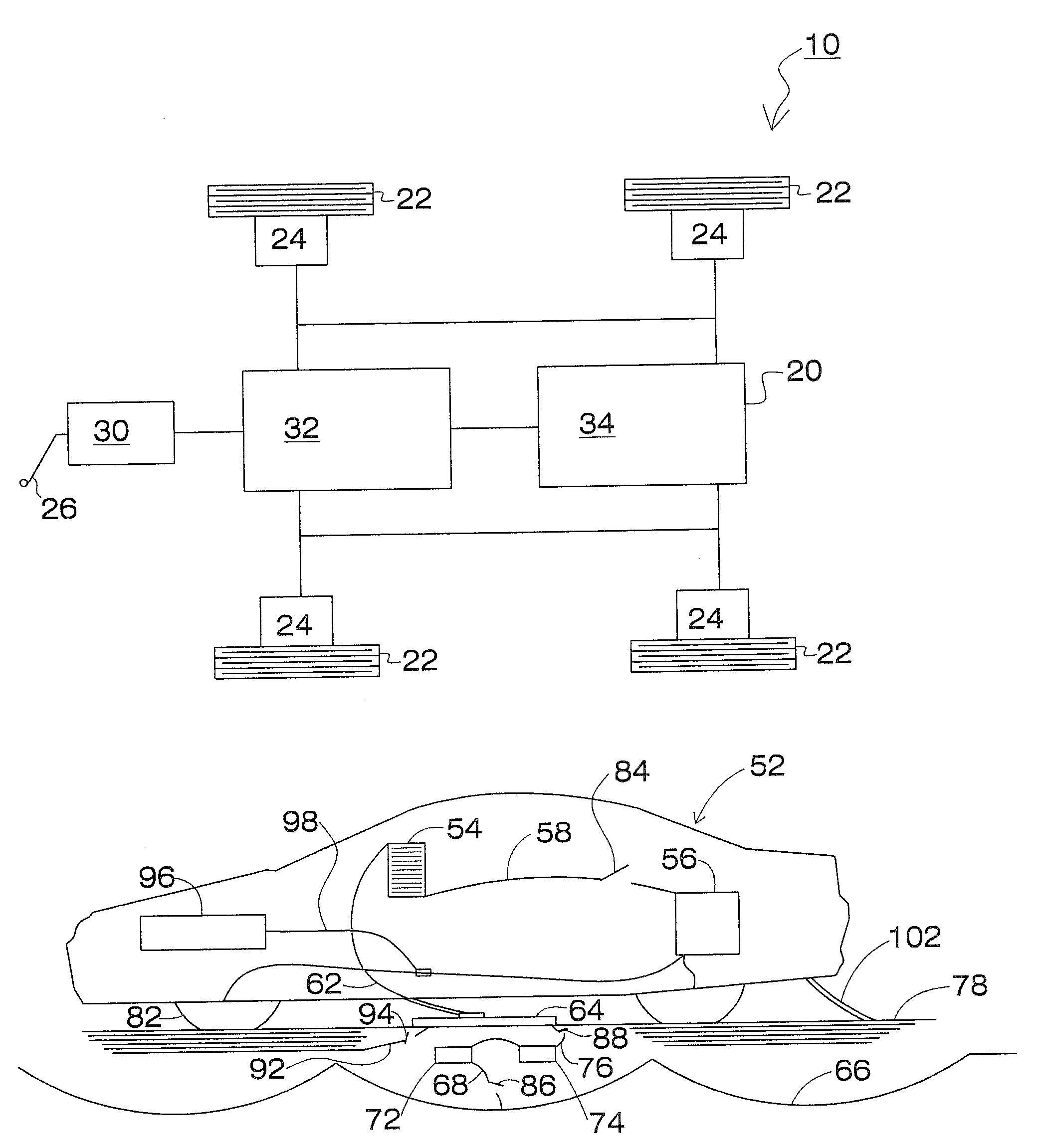
[0020]Thus, by way of the present system, not only is the charging rail providing intermittent charge to a vehicle, but the charging rail itself receives an intermittent charge from the power feed only as the vehicle completely conceals the charging rail. While the vehicle is passing over the charging rail the vehicle is protecting the rail because it will be built to provide the benefits of a “faraday cage” which keeps passengers safe inside an automobile. The vehicle being charged will have a built in path to ground. Therefore, while the vehicle is being charged it is providing lightning protection to the high voltage activity taking place beneath it. As quickly as the vehicle moves away from the charging rail all circuits invol

Problems solved by technology

Lightning poses a serious problem in all of the referenced systems.
Indeed, the damaging effect of a lightening strike, or other power surge, is a major obstacle for any electrically powered vehicle that receives power from either an overhead electric cable or from an electrified rails.
If a strong lightning bolt strikes a power supply cable or rail the electric surge can travel for miles and cause damage to both the attached vehicles and to the system of transformers that power the distribution lines.
This is a result of the fact that each unit length of exposed, charged rail has an equal o

Method used


Image

  • Method and Apparatus for Protecting Charging Devices from Surges and Lightening Strikes
  • Method and Apparatus for Protecting Charging Devices from Surges and Lightening Strikes
  • Method and Apparatus for Protecting Charging Devices from Surges and Lightening Strikes

Examples


Embodiment Construction

[0031]The present invention relates to a method and apparatus for charging electrically powered devices. In accordance with the invention, the device is powered by two storage or charge receiving devices. One of these devices is capable of receiving a substantial charge very rapidly while the other device requires a longer time to receive a charge. The advantage is that the powered device can be used almost instantly and continually while at the same time rebuilding electrical charge. The present invention further relates to a system for protecting the charging device from being damaged from an electrical surge, such as from a lightening strike.

Electric Vehicles and Charging Stations

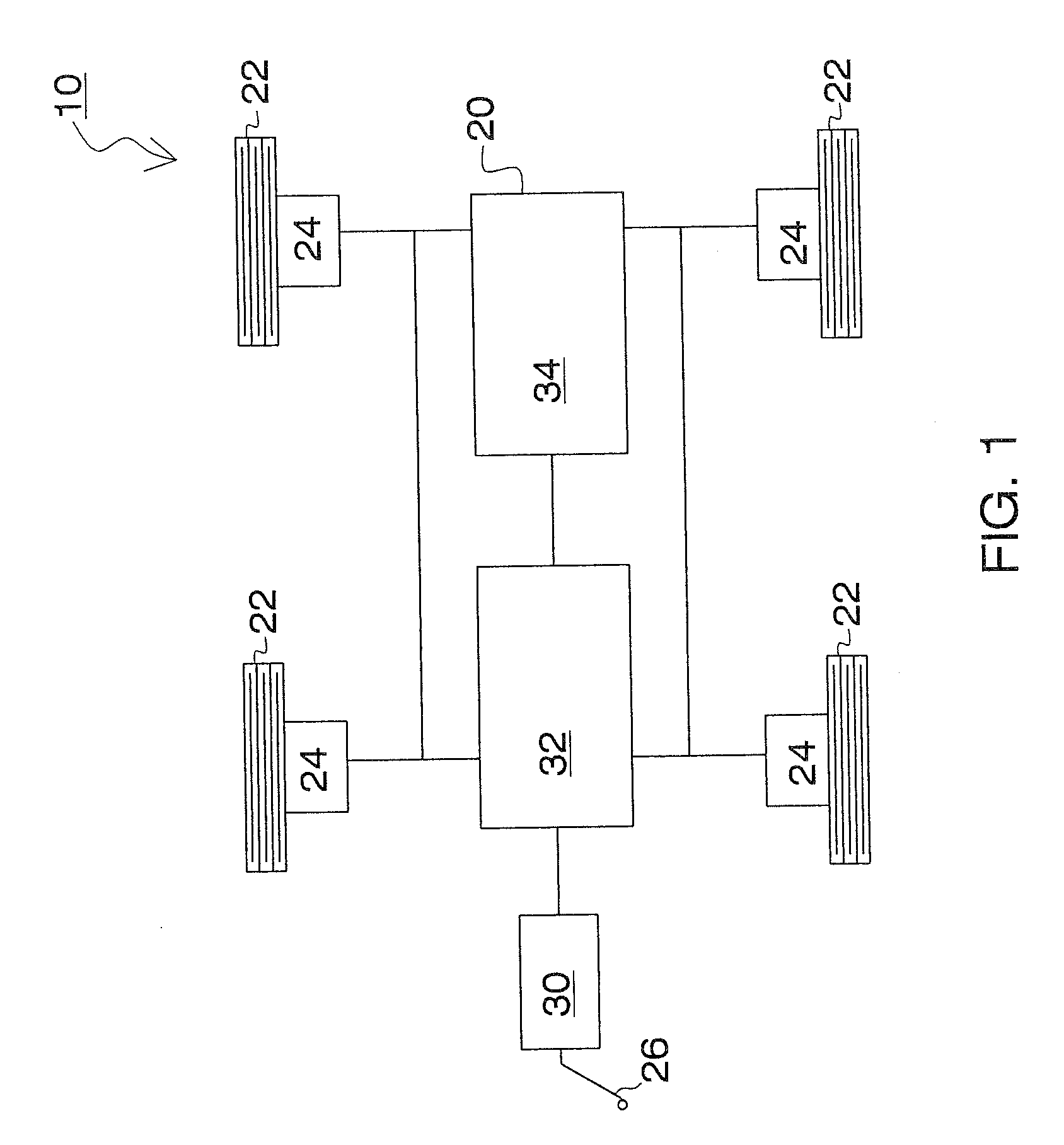
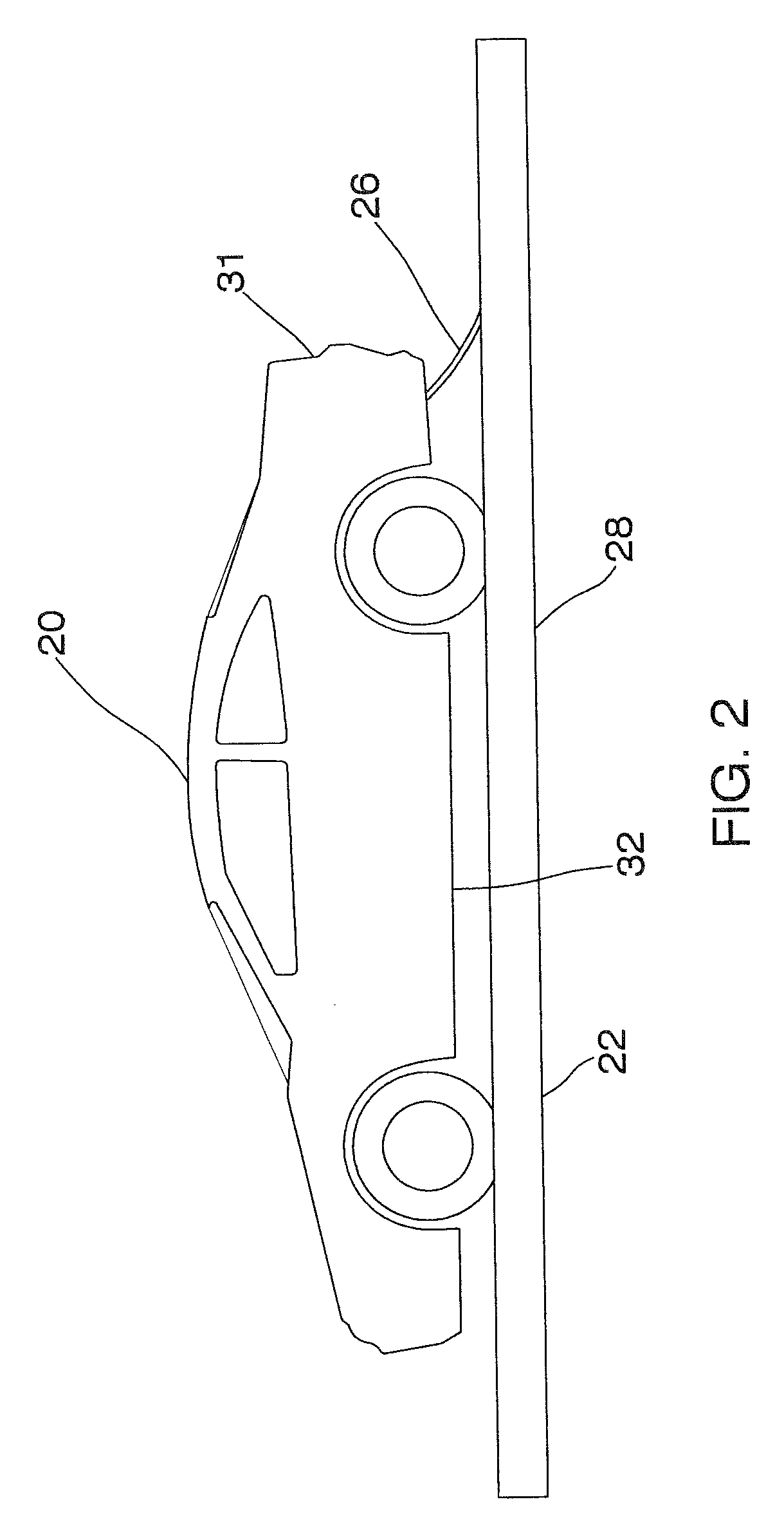
[0032]FIG. 1 is a schematic diagram illustrating the various components of the primary embodiment 10 of the present invention. As illustrated, the invention relates to a vehicle 20 that includes four independently operating wheels 22. In the preferred embodiment, these wheels are each powered by independ...


PUM


Abstract

Disclosed is a method and apparatus for charging electrically powered devices. In accordance with the invention, the device is powered by two storage or charge receiving devices. One of these devices is capable of receiving a substantial charge very rapidly while the other device requires a longer time to receive a charge. The advantage is that the powered device can be used almost instantly and continually while at the same time rebuilding electrical charge. The present invention further relates to a system for protecting the charging device from being damaged from an electrical surge, such as from a lightening strike.

Description

CROSS REFERENCE TO RELATED APPLICATIONS [0001]This application claims priority to co-pending utility application Ser. No. 12 / 134,722 filed on Sep. 24, 2008 and entitled “Method and Apparatus for Charging Electric Devices,” which in turn claims priority to provisional application Ser. No. 60 / 942,389. The contents of both these applications are fully incorporated herein by reference.BACKGROUND OF THE INVENTION[0002]1. Field of the Invention[0003]This invention relates to a method and apparatus for charging electric devices. More particularly, the present invention relates to a system for powering an electric vehicle that protects against lightening strikes and electrical surges.[0004]2. Description of the Background Art[0005]The use of electrically powered vehicle is known in the art. For example, U.S. Pat. No. 3,637,956 to Blackman discloses an electrical automobile transportation system. The system embodies exposed electrified conductors on the road and electrical current collectors...

Claims


Application Information

Patent Timeline
IPC IPC(8): H02J7/00
CPCB60L3/0046B60L11/005B60L11/1816B60L11/1833B60L11/1887B60L2220/44Y02T90/34B60L2260/28Y02T10/7022Y02T90/121Y02T90/125Y02T90/14B60L2240/36B60L50/40B60L53/14B60L53/36B60L58/40Y02T10/70Y02T10/7072Y02T90/12Y02T90/40
Inventor KISSEL, JR., WALDEMAR F.
Owner WFK & ASSOC
Why Eureka
Try Eureka