Endoscope objective lens and endoscope

a technology of endoscope and objective lens, which is applied in the field of endoscope objective lens and endoscope, can solve the problems of lateral chromatic aberration weakened, difficult to correct, and light ray height, and achieve the effect of sufficiently correcting lateral chromatic aberration and long back focal length

Inactive Publication Date: 2011-03-15
FUJI PHOTO OPTICAL CO LTD
View PDF5 Cites 86 Cited by
  • Summary
  • Abstract
  • Description
  • Claims
  • Application Information

AI Technical Summary

Benefits of technology

[0010]In view of the above-described circumstances, the invention provides an endoscope objective lens that has a long back focal length in comparison with a focal length and can sufficiently correct the lateral chromatic aberration.
[0015]In the above endoscope objective lens, the configuration of the respective lenses is appropriately selected. In particular, the second cemented lens is configured to satisfy the conditional expression (1), thereby sufficiently correcting the lateral chromatic aberration. Also, the whole system is configured to satisfy the conditional expression (2), thereby ensuring a long back focal length.
[0020]In the above endoscope objective lens, the configuration of the respective lenses is appropriately selected. In particular, the second cemented lens is configured to satisfy the conditional expression (1)′, thereby sufficiently correcting the lateral chromatic aberration. Also, the whole system is configured to satisfy the conditional expression (2), thereby ensuring a long back focal length.

Problems solved by technology

However, as the back focal length increases, the maximum height of light rays in this optical member decreases, and the effect of correction of the lateral chromatic aberration is weakened, thereby making it difficult to correct.
Therefore, it is not easy to correct the lateral chromatic aberration.

Method used


Image

  • Endoscope objective lens and endoscope
  • Endoscope objective lens and endoscope
  • Endoscope objective lens and endoscope

Examples


example 1

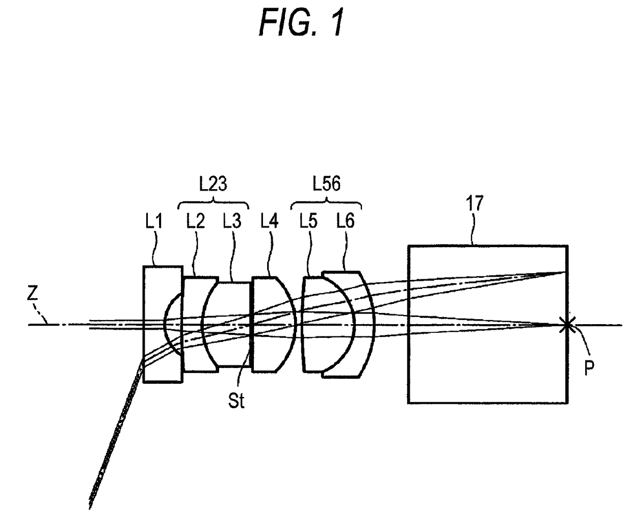
[0097]The specification values of an endoscope objective lens according to Example 1 are shown in Table 1. The configuration diagram of the lens of Example 1 is shown in FIG. 5. In FIG. 5, the left side is the object side, and the right side is the image side. In Table 1, the surface number ‘first’ is assigned to a surface that is a constituent element disposed closest to the object side, and surface numbers ‘i-th’ (i=1, 2, 3, . . . ) are assigned to respective surfaces while the surface number increases as advancing to the image side. Also, Ri denotes the radius of curvature of the i-th surface, and Di denotes a surface separation, on the optical axis Z, between the i-th surface and the (i+1)-th surface. Furthermore, ndj denotes an index of refraction of an j-th (j=1, 2, 3) lens or parallel flat plate 17 at a d-line (wavelength of 587.6 nm), wherein the lens number ‘first’ is assigned to the lens disposed closest to the object side, and lenses numbers increases as advancing to the ...

example 2

[0100]The specification values of an endoscope objective lens according to Example 2 are shown in Table 2. The configuration diagram of the lens of Example 2 is shown in FIG. 6. The symbols Ri and Di shown in FIG. 6 correspond to Ri and Di shown in Table 2.

[0101]

TABLE 2EXAMPLE 2Surface numberRiDindjνdj1∞0.381281.8830040.820.72560.3050438.24410.785641.9228618.94−3.00600.381281.8348142.7510.89370.021796 (Aperture diaphragm)∞0.038137∞1.004791.6204160.38−1.23450.1089495.30690.980451.6204160.310−1.10580.381282.1435217.811−1.83640.6552012∞3.000001.5163364.1Image plane∞

example 3

[0102]The specification values of an endoscope objective lens according to Example 3 are shown in Table 3. The configuration diagram of the lens of Example 3 is shown in FIG. 7. The symbols Ri and Di shown in FIG. 7 correspond to Ri and Di shown in Table 3.

[0103]

TABLE 3EXAMPLE 3Surface numberRiDindjνdj19.06710.396692.0095029.420.71310.31774315.02540.396691.8348142.741.17450.919801.9228618.95∞0.039676 (Aperture diaphragm)∞0.020427−11.33390.916351.6204160.38−1.26950.1133494.97331.024321.6204160.310−1.10390.396692.1435217.811−1.86020.7338912∞3.000001.5163364.1Image plane∞


PUM


Abstract

An endoscope objective lens includes, in order from an object side, a negative first lens, a first cemented lens, an aperture diaphragm, a positive fourth lens and a second cemented lens. The negative first lens has a concave surface directed to an image side. The first cemented lens is formed by cementing a second lens and a third lens. One of the second and third lenses is positive and. The other is negative. The positive fourth lens includes a flat surface or a surface having a larger absolute value in radius of curvature, directed to the object side. The second cemented lens is formed by cementing a positive fifth lens and a negative sixth lens in order from the object side. The second cemented lens has a positive refractive power as a whole. The endoscope objective lens satisfies the following conditional expressions (1) and (2).f2×v5-v6RA×(Bf+d6 / n6)>10(1)Bf / f>2.5(2)

Description

CROSS-REFERENCE TO RELATED APPLICATIONS[0001]This application is based upon and claims the benefit of priority from the Japanese Patent Application Nos. 2007-101588 and 2007-101589 both filed on Apr. 9, 2007; the entire contents of which are incorporated herein by reference.BACKGROUND OF THE INVENTION[0002]1. Technical Field[0003]The invention relates to an endoscope objective lens and an endoscope, and more particularly, to an endoscope objective lens that is appropriate for use in such a configuration that a prism for deflecting a light path or the like is disposed between the endoscope objective lens and an image formation surface, and an endoscope including the endoscope objective lens.[0004]2. Description of the Related Art[0005]Generally, endoscopes are used for observing the inside of a patient's body, performing treatment for a patient, and the like. As the endoscope, widely used is a direct-view type endoscope that is used to observe in the longitudinal direction of an inse...

Claims


Application Information

Patent Timeline
Patent Type & Authority Patents(United States)
IPC IPC(8): G02B9/00
CPCG02B23/243
Inventor MIYANO, HITOSHI
Owner FUJI PHOTO OPTICAL CO LTD
Why Eureka
Try Eureka