Self-cleaning shaker

a shaker and self-cleaning technology, applied in the direction of grading, chemistry apparatus and processes, gas current separation, etc., can solve the problems of time-consuming and expensive mud evaluation and mixture process, too light may not protect, and too heavy may over-invade the formation

Inactive Publication Date: 2011-03-22
MI
View PDF13 Cites 9 Cited by
  • Summary
  • Abstract
  • Description
  • Claims
  • Application Information

AI Technical Summary

Problems solved by technology

Drilling mud that is too light may not protect the formation from blow outs, and drilling mud that is too heavy may over invade the formation.
Because the mud evaluation and mixture process is time consuming and expensive, drillers and service companies prefer to reclaim the returned drilling mud and recycle it for continued use.
As drilling fluid is processed, residual drilling waste (e.g., high density fluids and particulate matter), may become stuck or entrained on the shaker screens and other internal shaker components.
As the amount of residual drilling waste increases, the efficiency of the shale shaker may decrease due to, for example, clogged screens, clogged outlet lines, and / or “gummed up” internal components.
These processes are both time intensive and labor intensive.

Method used


Image

  • Self-cleaning shaker
  • Self-cleaning shaker
  • Self-cleaning shaker

Examples


Embodiment Construction

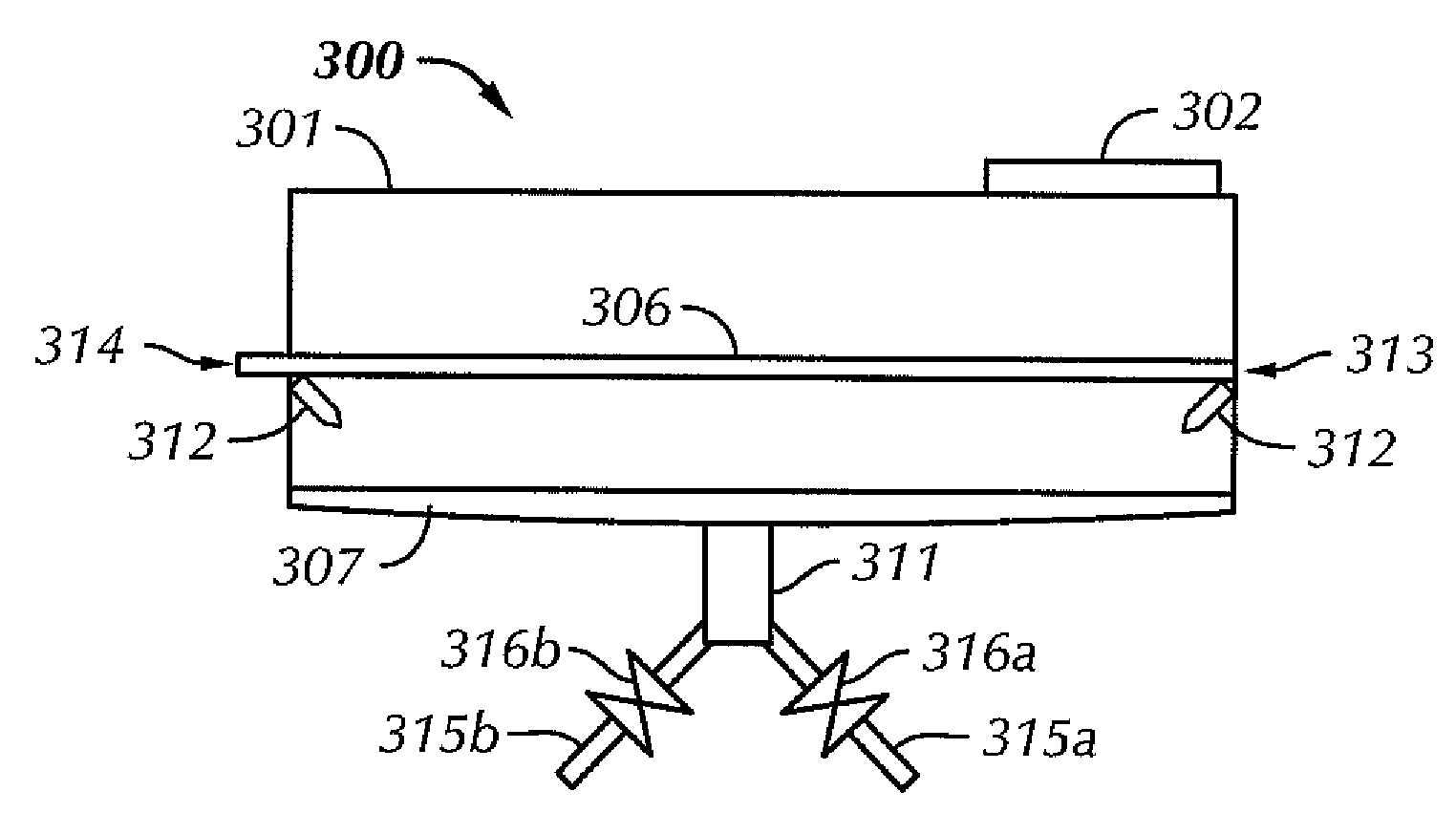
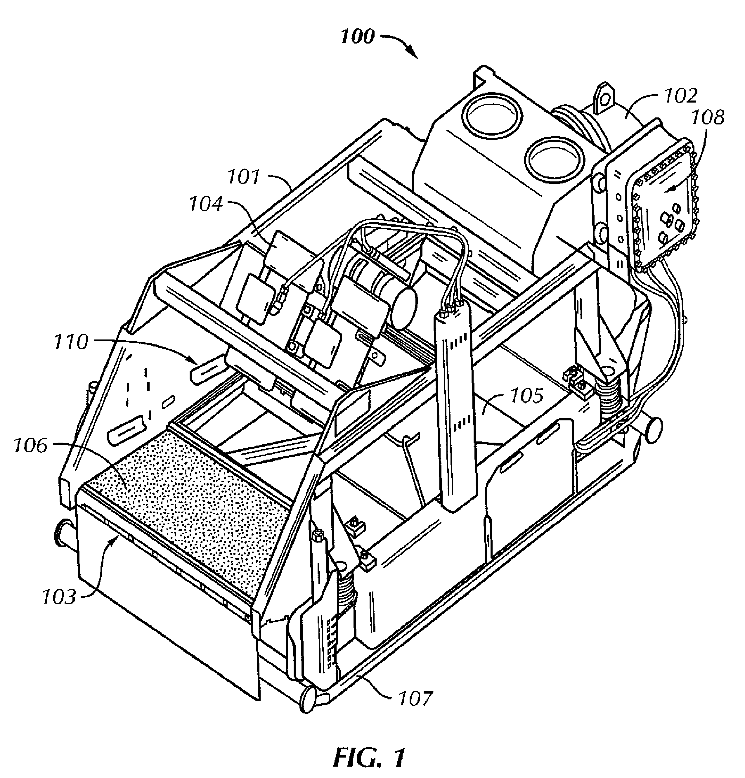
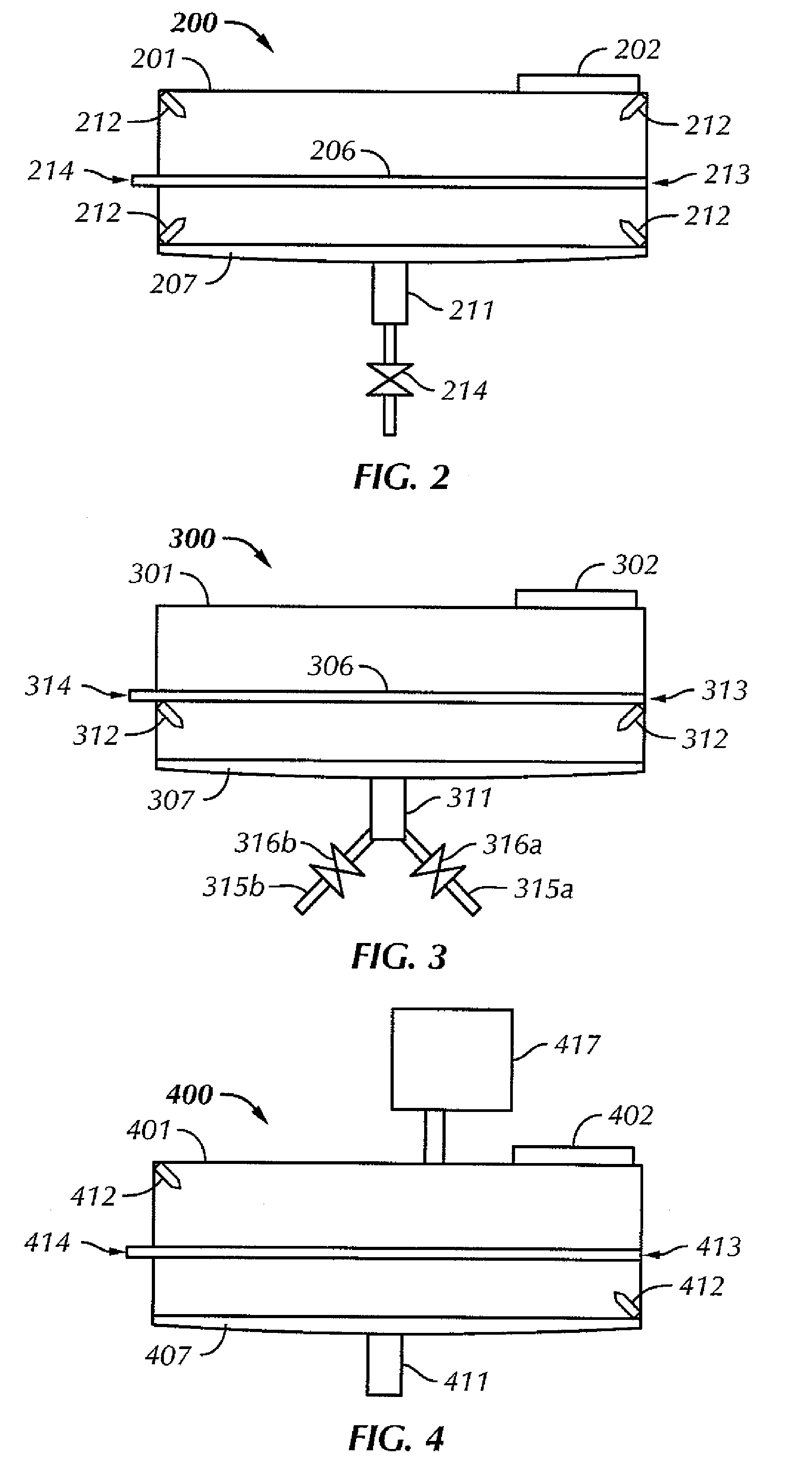
[0023]Generally, embodiments disclosed herein relate to apparatuses and methods for cleaning vibratory shakers. Furthermore, apparatuses and methods disclosed herein may include at least one spray nozzle and / or vibratory sump for the automated cleaning of vibratory shakers.

[0024]Referring initially to FIG. 1, a top perspective view of a vibratory separator 100 in accordance with one embodiment of the present disclosure is shown. In this embodiment, vibratory separator 100 includes a housing 101 defining a drilling material inlet 102, a drilling material discharge area 103, and an inner section 110. Vibratory separator 100 also includes at least one actuator 104 (e.g., a motor, a motor system, or a motor control device). In this embodiment, actuator 104 is coupled to a rotary motor (not shown), which upon engagement, imparts a vibratory motion to a basket 105 that is disposed within housing 101.

[0025]Securely attached to basket 105 is at least one screen assembly 106. Screen assembly...


PUM


Abstract

A vibratory separator including a housing having a drilling material inlet and at least one basket, at least one screen assembly configured to be disposed in the at least one basket, an actuator connected to the at least one basket, wherein the actuator provides vibratory motion to the at least one basket, a sump configured to receive drilling material that passes through the at least one screen assembly, and at least one spray nozzle for cleaning the vibratory separator is disclosed. A method for cleaning a vibratory separator including providing instructions to a programmable logic controller to activate at least one spray nozzle disposed on the vibratory separator is also disclosed. A method of retrofitting a vibratory separator including installing at least one spray nozzle in a vibratory separator, installing a programmable logic controller on the vibratory separator, and providing instructions to the programmable logic controller to activate at least one spray nozzle disposed on the vibratory separator is disclosed.

Description

[0001]The present application claims priority to U.S. Provisional Patent Application Ser. No. 60 / 827,560, filed on Sep. 29, 2006, and is hereby incorporated by reference in its entirety.BACKGROUND[0002]1. Field of the Disclosure[0003]The present disclosure generally relates to methods and apparatuses for cleaning vibratory shakers and vibratory shaker components. More specifically, the present disclosure relates to automated methods and apparatuses for cleaning vibratory shakers and vibratory shaker components.[0004]2. Background[0005]Oilfield drilling fluid, often called “mud,” serves multiple purposes in the industry. Among its many functions, the drilling mud acts as a lubricant to cool rotary drill bits and facilitate faster cutting rates. Typically, the mud is mixed at the surface and pumped downhole at high pressure to the drill bit through a bore of the drillstring. Once the mud reaches the drill bit, it exits through various nozzles and ports where it lubricates and cools th...

Claims


Application Information

Patent Timeline
Patent Type & Authority Patents(United States)
IPC IPC(8): B07B1/55
CPCB07B1/42B07B1/46B07B1/55B07B1/28
Inventor JONES, BRADLEY N.CARR, BRIAN S.
Owner MI
Why Eureka
Try Eureka