Static lamination micro mixer

Active Publication Date: 2011-03-22
EHRFELD MIKROTECHNIK BTS GMBH
View PDF34 Cites 14 Cited by
  • Summary
  • Abstract
  • Description
  • Claims
  • Application Information

AI Technical Summary

Benefits of technology

The advantages achieved by the invention consist in the fact that the static lamination micro-mixer can be produced economically, is easy to clean and the fl

Problems solved by technology

In the case of the micro-mixers constructed from plates, the plates are preferably permanently connected to one another and, as a result, the micro-structures are no longer freely accessible; cleaning of the micro-mixers described is therefore not poss

Method used


Image

  • Static lamination micro mixer
  • Static lamination micro mixer
  • Static lamination micro mixer

Examples


Embodiment Construction

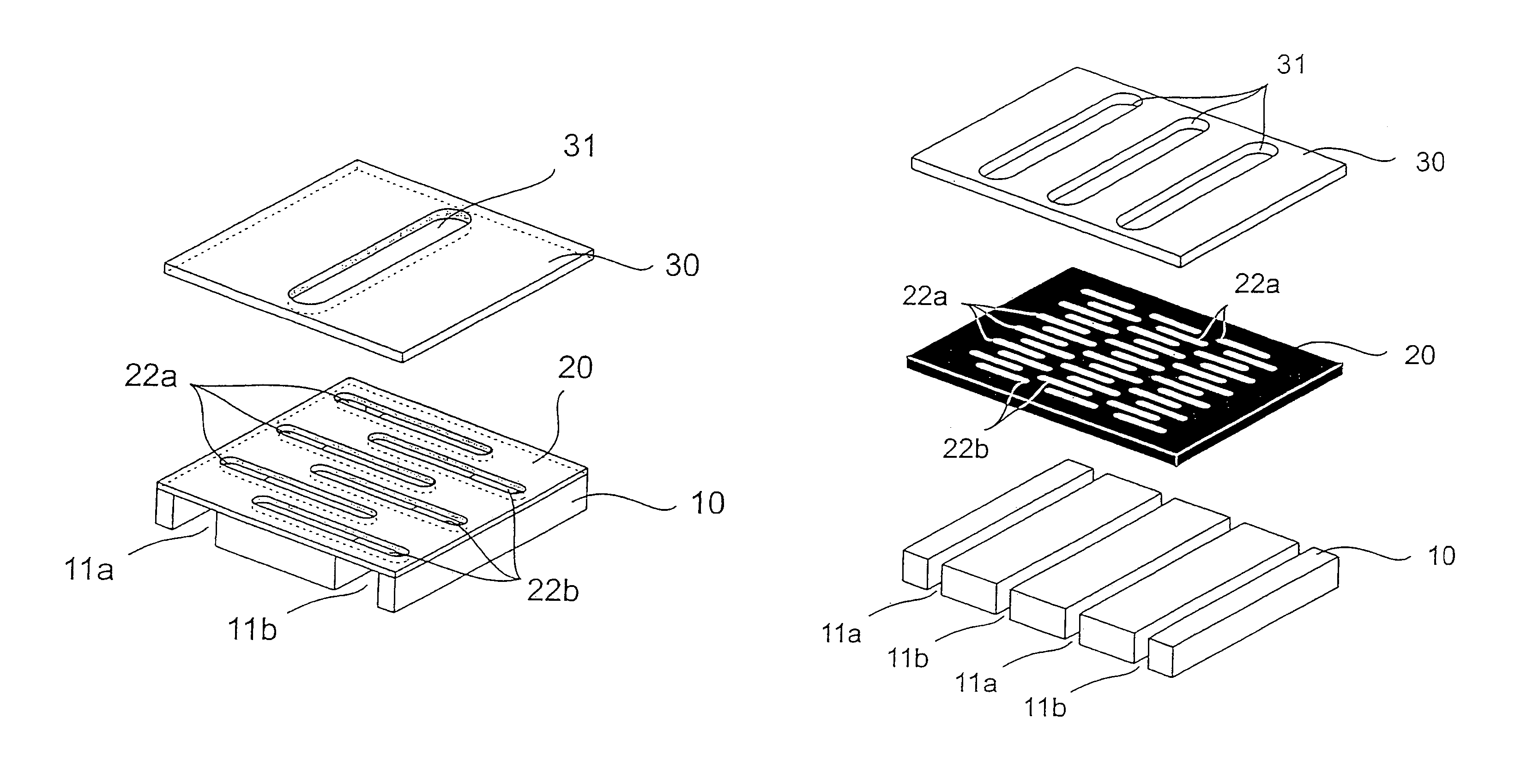
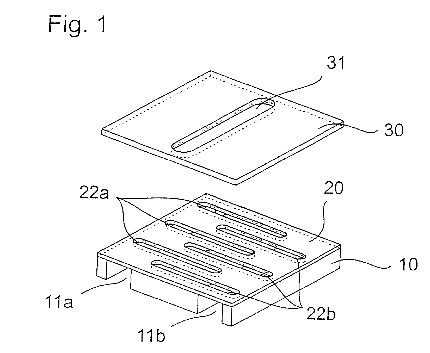
FIG. 1 shows a schematic illustration of a static lamination micro-mixer comprising lower part 10, a slotted plate 20 and an aperture plate 30. The lower part 10 contains the feed channel 11a for the fluid A and the feed channel 11b for the fluid B. The slotted plate 20 has slot openings 22a and 22b for the fluids A and B, which are fed from the feed channel 11a and 11b. Above the slotted plate 30 there is the aperture plate 30 having an aperture slot 31. In this case, the aperture plate 30 covers the outer region of the slot openings 22a and 22b, the central region of the slot openings 22a and 22b overlapping the aperture slot 31 and remaining free as a result.

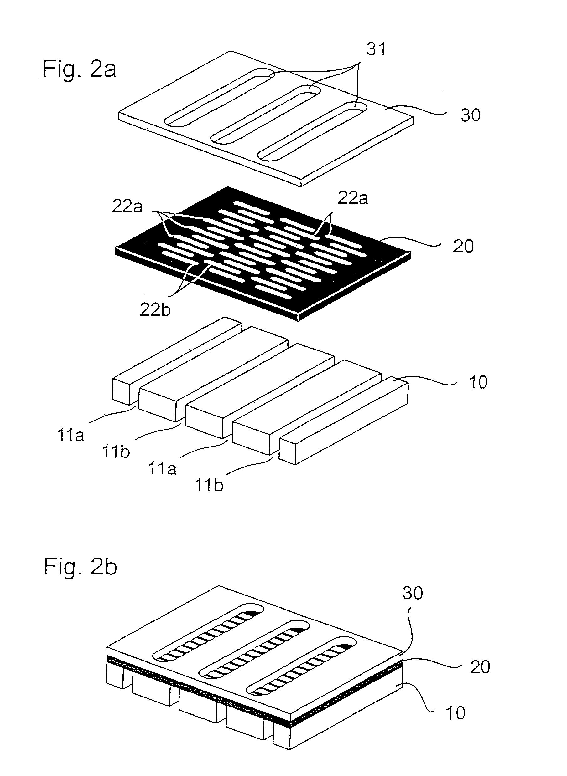
FIG. 2a shows the exploded illustration of a static micro-mixer comprising lower part 10, feed channels 11a and 11b, slotted plate 20 and aperture plate 30. The feed channels 11a and 11b in each case contain the fluids A and B; above these feed channels there is the slotted plate 20 having the slot openings 22a and 22b. Locat...


PUM


Abstract

Static lamination micro mixer comprising at least one slotted plate having slot openings and an aperture plate having aperture slots arranged above the slotted plate.

Description

This is a 371 of PCT / EP2003 / 013603 filed 3 Dec. 2003 (international filing date).The invention relates to a micro-mixer for mixing, dispersing, emulsifying or suspending at least two fluid phases, it being necessary for this micro-mixer to have at least one slotted plate having slot openings and an aperture plate having aperture slots arranged above the former. The slot openings in the slotted plate(s) and aperture plate(s) are formed as continuous openings. The opening can be shaped as desired; the opening preferably has a simple geometry (for example a hole or rectangular slot).BACKGROUND OF THE INVENTIONStatic micro-mixers are key elements in micro-reaction technology. Static micro-mixers use the principle of multi-lamination, in order in this way to achieve rapid mixing of fluid phases by means of diffusion. A geometric configuration of alternately arranged lamellae makes it possible to ensure good mixing in the microscopic range. Multi-lamination mixers made of structured and p...

Claims


Application Information

Patent Timeline
IPC IPC(8): B01F5/00B81B1/00B01F5/06B01F13/00
CPCB01F5/0604B01F13/0066B01F13/0067Y10S366/03B01F25/422B01F33/3012B01F33/30121B01F25/20B01F25/40B01F33/00
Inventor EHRFELD, WOLFGANGKROSCHEL, MATTHIASMERKEL, TILLHERBSTRITT, FRANK
Owner EHRFELD MIKROTECHNIK BTS GMBH
Why Eureka
Try Eureka