
Sewing machine

a sewing machine and spreader technology, applied in the field of sewing machines, can solve the problems of time-consuming work for users, deterioration of the elasticity of the lever, and unfirm holding of the spreader, and achieve the effect of convenient attachment or removal

Inactive Publication Date: 2011-03-29
JUKI CORP
View PDF11 Cites 1 Cited by
  • Summary
  • Abstract
  • Description
  • Claims
  • Application Information

AI Technical Summary

Benefits of technology

Facilitates quick and secure attachment / detachment of the spreader, preventing falling and ensuring stable holding without relying on elastic structures, thus enhancing operational efficiency and reducing wear-related issues.

Problems solved by technology

However, in a case in which the spreader is attached to the top covering shaft with the screw, it is necessary to fasten or to loosen the screw with a driver or a wrench when attaching or detaching the spreader, which is a time-consuming work for a user.
In a case in which the spreader is attached to the lever by utilizing the elasticity of the plastic lever, on the other hand, there has been a problem that the elasticity of the lever deteriorates while being used, resulting in an unfirm holding of the spreader.

Method used


Image

  • Sewing machine
  • Sewing machine
  • Sewing machine

Examples


Embodiment Construction

[0016]Hereinafter, an exemplary embodiment of the invention will be explained with reference to the drawings. The following exemplary embodiment does not limit the scope of the invention.

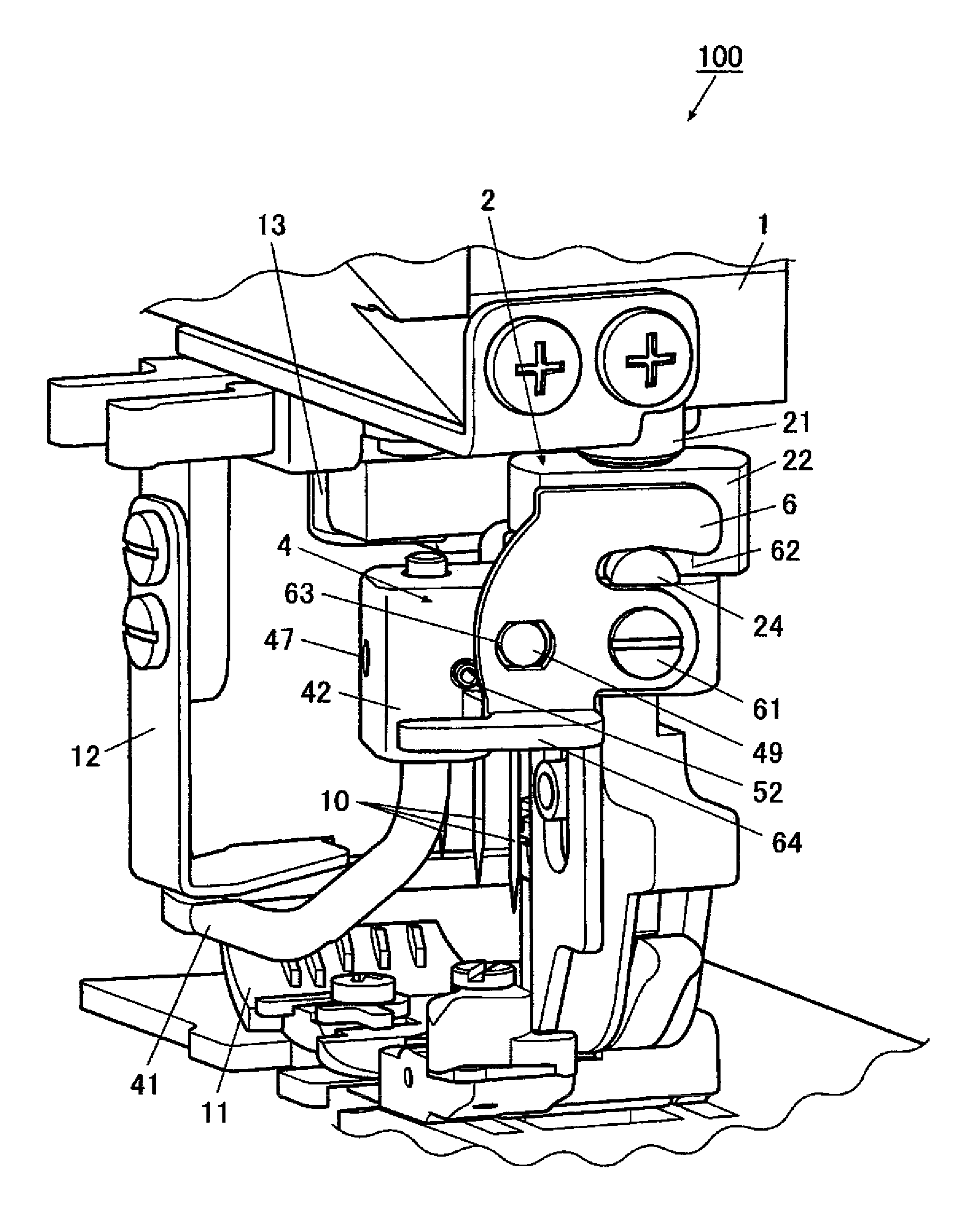
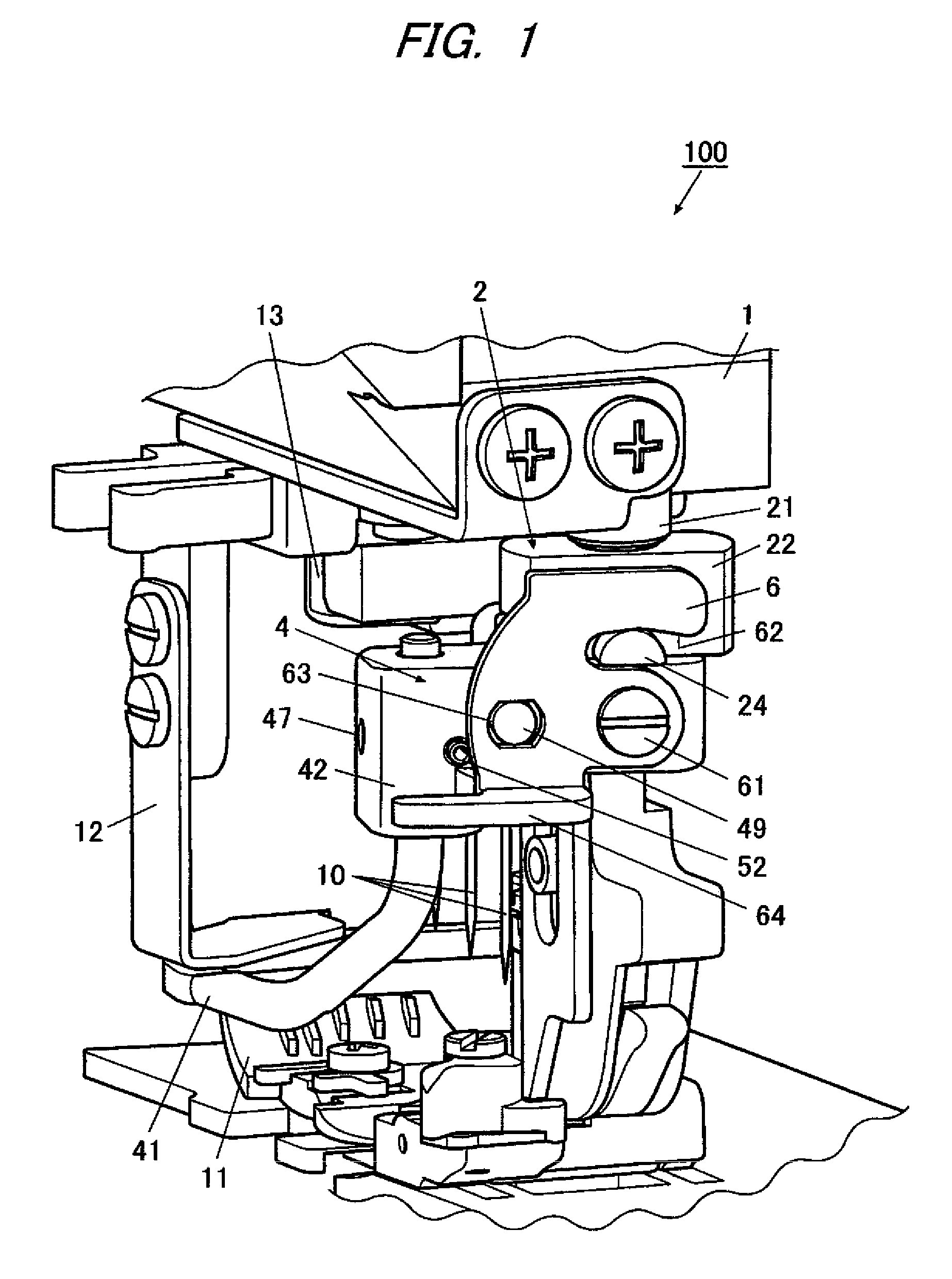
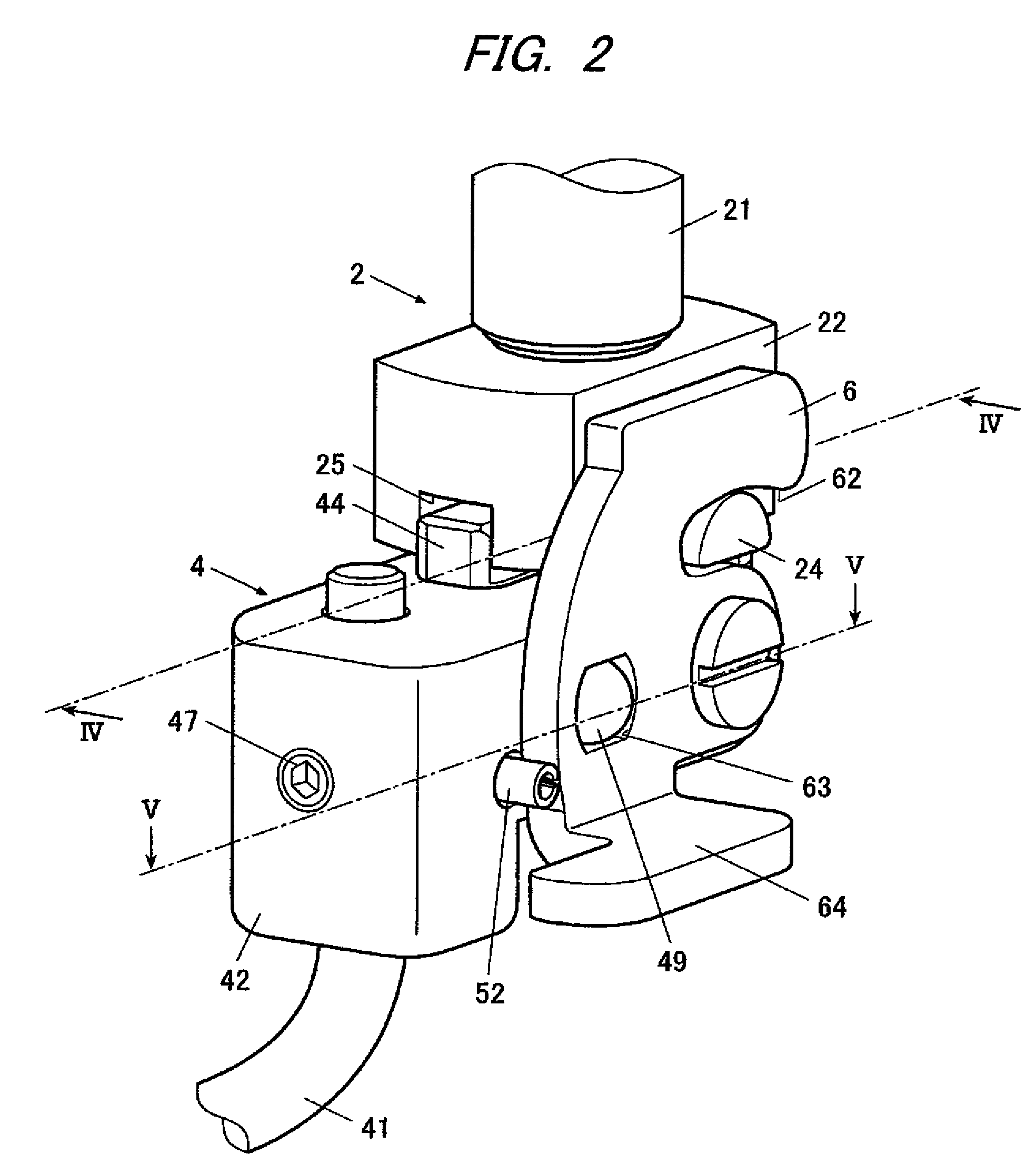
[0017]As shown in FIG. 1, a sewing machine 100 includes a top covering shaft mechanism 2 disposed near a jaw portion of a sewing machine body 1, a spreader mechanism 4 detachably attached to the top covering shaft mechanism 2 from below, an operating member 6 attached to the spreader mechanism 4, a plurality of needles 10 respectively having an eye through which a corresponding needle thread is inserted and are vertically moved by a sewing machine motor to insert the needle threads into a workpiece, a presser 11 disposed below the needles 10 to press the workpiece against a throat plate, and thread guides 12, 13 which guide a covering thread to the spreader mechanism 4. The operating member 6 is rotatable between a position at which the spreader mechanism 4 is locked with respect to the top covering...


PUM


Abstract

A sewing machine is provided. The sewing machine includes a top covering shaft mechanism, a spreader mechanism detachably attached to the top covering shaft mechanism from below and operable to catch a covering thread and to interlace the covering thread with a needle thread inserted into a needle to form covering stitches, and an operating member having a hook portion and rotatably attached to either one of the top covering shaft mechanism and the spreader mechanism. The other of the top covering shaft mechanism and the spreader mechanism has a protrusion with which the hook portion is engageable. The operating member is rotatable between a position at which the hook portion engages with the protrusion to lock the spreader mechanism with respect to the top covering shaft mechanism and another position at which the spreader mechanism is detachable from the top covering shaft mechanism.

Description

CROSS-REFERENCE TO RELATED APPLICATION[0001]The present application claims priority from Japanese Patent Application No. 2007-227821 filed on Sep. 3, 2007, the entire content of which is incorporated herein by reference.FIELD OF INVENTION[0002]The present invention relates to a sewing machine which is operable to form covering stitches.DESCRIPTION OF RELATED ART[0003]Related art sewing machines have three needles, through which needle threads are inserted respectively and which are arranged in a direction intersecting a cloth feeding direction, and a spreader with which a covering thread is controlled. More specifically, the spreader carries out, synchronously with a vertical motion of the three needles, a circular motion above a workpiece from a side of the needles toward a front of the needles to interlace the covering thread with the three needle threads. Synchronously with the interlacing operation of the spreader, a looper is rotated to interlace a looper thread with the needle...

Claims


Application Information

Patent Timeline
Patent Type & Authority Patents(United States)
IPC IPC(8): D05B61/00D05B1/08
CPCD05B61/00
Inventor SAKANO, MASAHIRO
Owner JUKI CORP
Learn More