Power-generating device for electro-magnetic or any electric engine

a technology of power generation device and engine, applied in the field of engines, can solve the problem of no system producing power for engines, and achieve the effect of retaining effectiveness and being easy to manufacture and maintain

Inactive Publication Date: 2011-03-29
ELMALEH SHIMON
View PDF7 Cites 35 Cited by
  • Summary
  • Abstract
  • Description
  • Claims
  • Application Information

AI Technical Summary

Benefits of technology

[0009]The electro-magnetic means generates an electro-motive force between the first and second openings and its corresponding magnetic body when synchronized by the distributor. Wherein switching the magnetic polarity between the first and second openings forces the piston to move upward and downward within its respective cylinders, thus rotating the crankshaft means in a predetermined direction continuously after the initial activation of the crankshaft means by applying a short period of an electrical force. The electro-magnetic means being affixed to the housing structure.
[0012]It is yet another object of this invention to provide such a device that is inexpensive to manufacture and maintain while retaining its effectiveness.

Problems solved by technology

There are no systems that produce power for engines, and especially for electro-magnetic engines.

Method used


Image

  • Power-generating device for electro-magnetic or any electric engine
  • Power-generating device for electro-magnetic or any electric engine
  • Power-generating device for electro-magnetic or any electric engine

Examples


Embodiment Construction

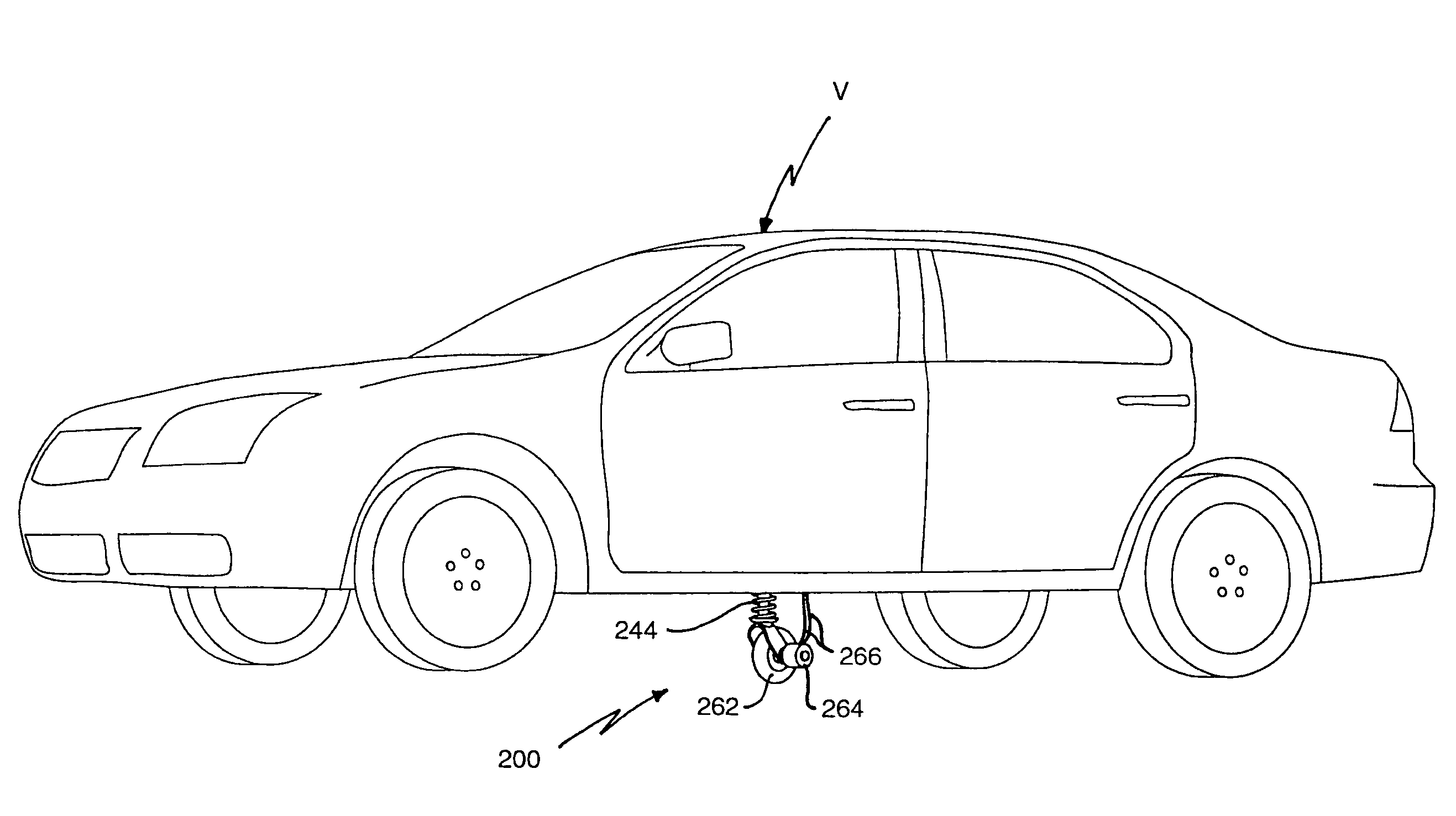
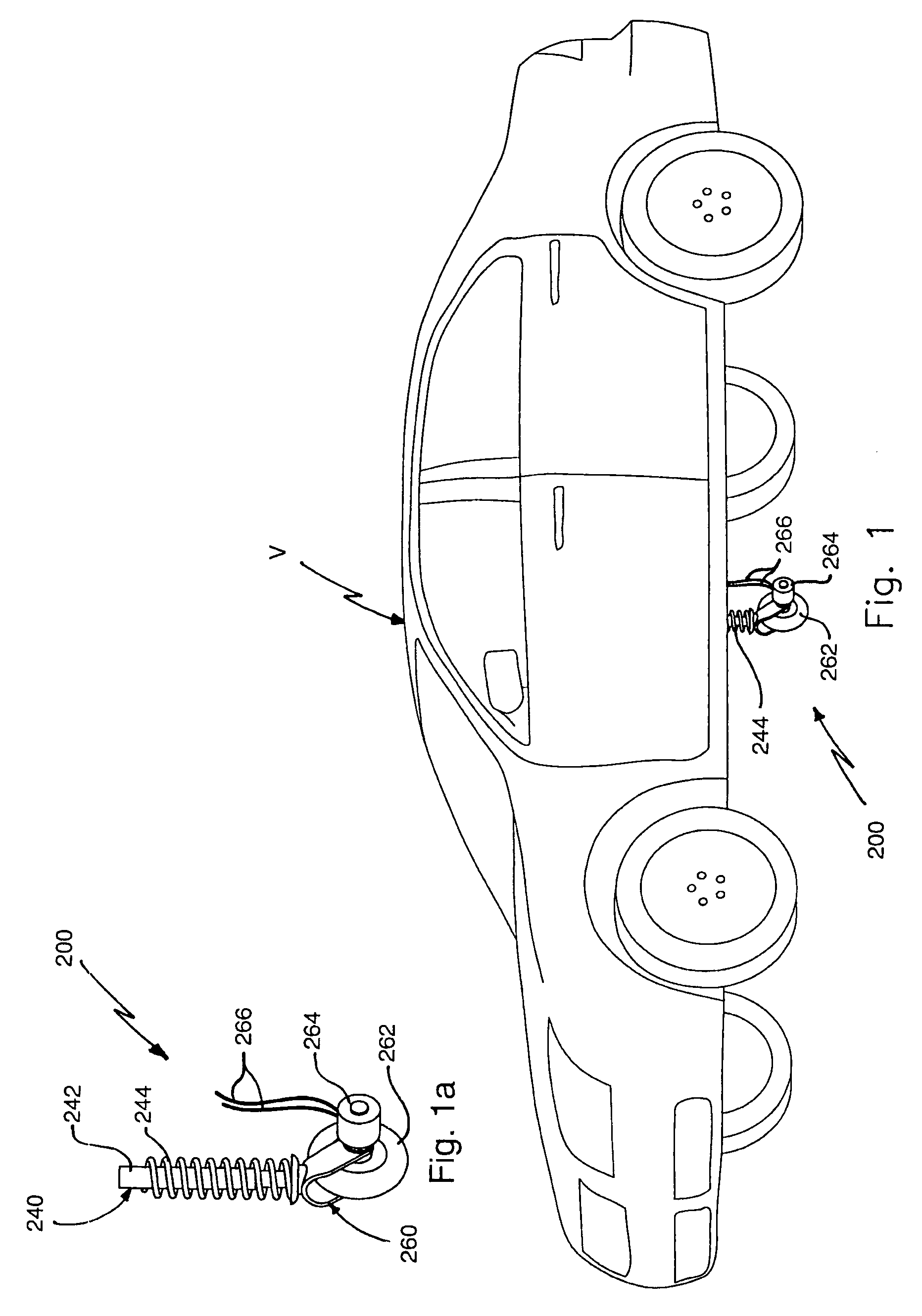
[0023]Referring now to the drawings, instant invention 200 is defined as a power-generating device for an engine, such as electro-magnetic engine 10.

[0024]As seen in FIGS. 1 and 1A, instant invention 200 is a power-generating device. It comprises shaft assembly 240 that is mounted onto vehicle V. Shaft assembly 240 comprises elongated shaft 242 that comprises shock-absorbing means, such as spring 244. Wheel assembly 260 comprises at least one wheel 262 that is mounted onto shaft assembly 240. Wheel 262 rotates upon a surface on which vehicle V is traveling upon, to generate power at electrical generator 264, or an alternator, for an engine of vehicle V. Such a surface can be, but is not limited to, a road, expressway, street, uneven path, or even a rail track. Instant invention 200 generates the power and provides it to a source of rechargeable battery power of the engine via cables 266.

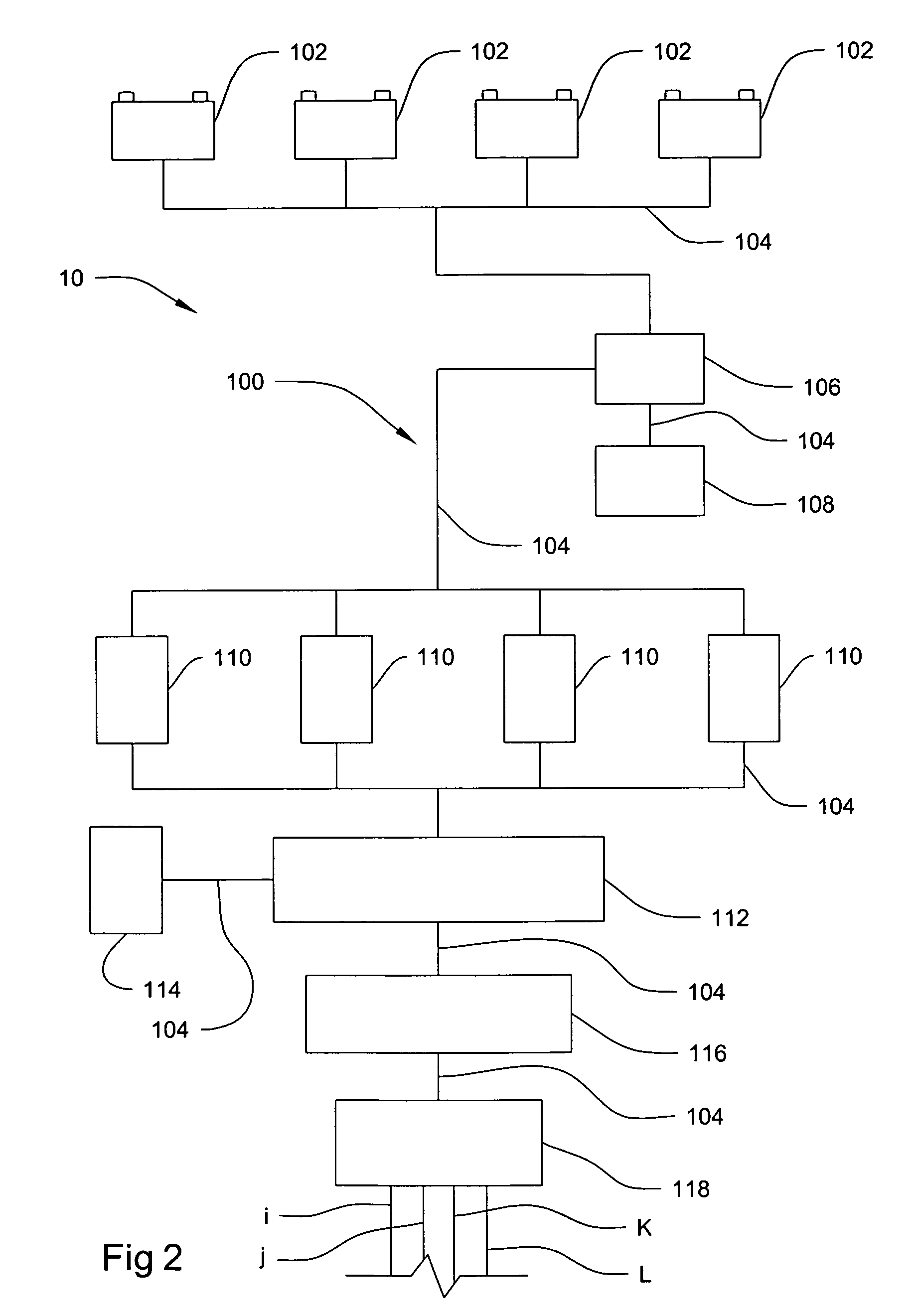
[0025]In the preferred embodiment, the engine is electro-magnetic engine 10 that consists of two ...


PUM


Abstract

The instant invention is a power-generating device, comprising a shaft assembly having an elongated shaft that is mounted onto a vehicle. The elongated shaft comprises shock-absorbing means. A wheel assembly is mounted onto the shaft assembly. The wheel assembly comprises at least one wheel and an electrical generator. The wheel rotates upon a surface on which the vehicle is traveling upon to generate power at the electrical generator or alternator for an engine of the vehicle. The electrical generator generates the power to a source of rechargeable battery power of the engine.

Description

BACKGROUND OF THE INVENTION[0001]1. Field of the Invention[0002]The present invention relates to engines, and more particularly, to power-generating devices for engines.[0003]2. Description of the Related Art[0004]Most vehicles, and especially automobiles, comprise internal combustion engines that run on gasoline. Other vehicles run by electrical means or hybrid means. There are no systems that produce power for engines, and especially for electro-magnetic engines.[0005]Applicant believes that one of the closest references corresponds to Applicant's own U.S. Pat. No. 7,105,958 issued on Sep. 12, 2006 for an Electro-magnetic engine. However, it differs from the present invention because in that invention Applicant taught an electro-magnetic engine and not a power-generating device for the engine. More specifically, Applicant taught an electro-magnetic engine in which the motive force is electro-magnetism. The electro-magnetic engine comprises a housing structure, cylinder assembly, c...

Claims


Application Information

Patent Timeline
Patent Type & Authority Patents(United States)
IPC IPC(8): B60L9/00H02K33/00
CPCB60K25/00B60L2200/26
Inventor ELMALEH, SHIMON
Owner ELMALEH SHIMON
Why Eureka
Try Eureka