Step-up DC-DC converter

a dc-dc converter and step-up technology, applied in the direction of electric variable regulation, process and machine control, instruments, etc., can solve the problems of low overall conversion efficiency, difficult to obtain high efficiency power conversion and non-negligent current consumption for charging and discharging the switching element, so as to prevent a voltage from being output at the output terminal, improve power conversion efficiency, and reduce current consumption under a light load

Inactive Publication Date: 2011-03-29
RICOH ELECTRONIC DEVICES CO LTD
View PDF8 Cites 0 Cited by
  • Summary
  • Abstract
  • Description
  • Claims
  • Application Information

AI Technical Summary

Benefits of technology

[0009]A preferred embodiment of the present invention may provide a step-up DC-DC converter able to change a control scheme of a second switching element when a load current is under a heavy load and a light load, and provide high efficiency power conversion under both the heavy load and the light load.
[0020]According to the above embodiment, with a heavy load, the switching DC-DC converter controls the first switching element in synchronization with the second switching element, and this allows formation of channels in the first switching element and the second switching element, and thus, reducing resistance of an ON state, and high efficiency power conversion can be performed even under a heavy load.
[0022]when the step-up DC-DC converter is in a standby state and the second switching elements are switched OFF, charging the smoothing capacitor with a direct current is prevented.
[0023]According to the above embodiment, since two second switching elements are connected in series, the back gate of one second switching element is connected to the inductor, and the back gate of the other second switching element is connected to the smoothing capacitor, when the second switching elements are switched OFF, it is possible to prevent a voltage from being output at an output terminal.
[0024]According to an embodiment of the present invention, since the control scheme of the second switching element is changed according to the load current, and the second switching element is kept switched OFF under a light load, the charging and discharging current occurring when the second switching element switches is reduced, current consumption under a light load can be reduced, and it is possible to improve power conversion efficiency under the light load.

Problems solved by technology

However, although high power conversion efficiency can be obtained under a heavy load, a charging and discharging current occurring when the second switching element switches under a light load becomes non-negligible, so that the overall conversion efficiency lowers.
However, in the method disclosed in reference 1, although high efficiency power conversion can be obtained under a heavy load, since the first switching element and the second switching element are both switched on under a light load, while switching element resistance inside a circuit can be reduced, current consumption for charging and discharging the switching element becomes non-negligible, and it is difficult to obtain high efficiency power conversion under a light load.

Method used


Image

  • Step-up DC-DC converter
  • Step-up DC-DC converter
  • Step-up DC-DC converter

Examples


first embodiment

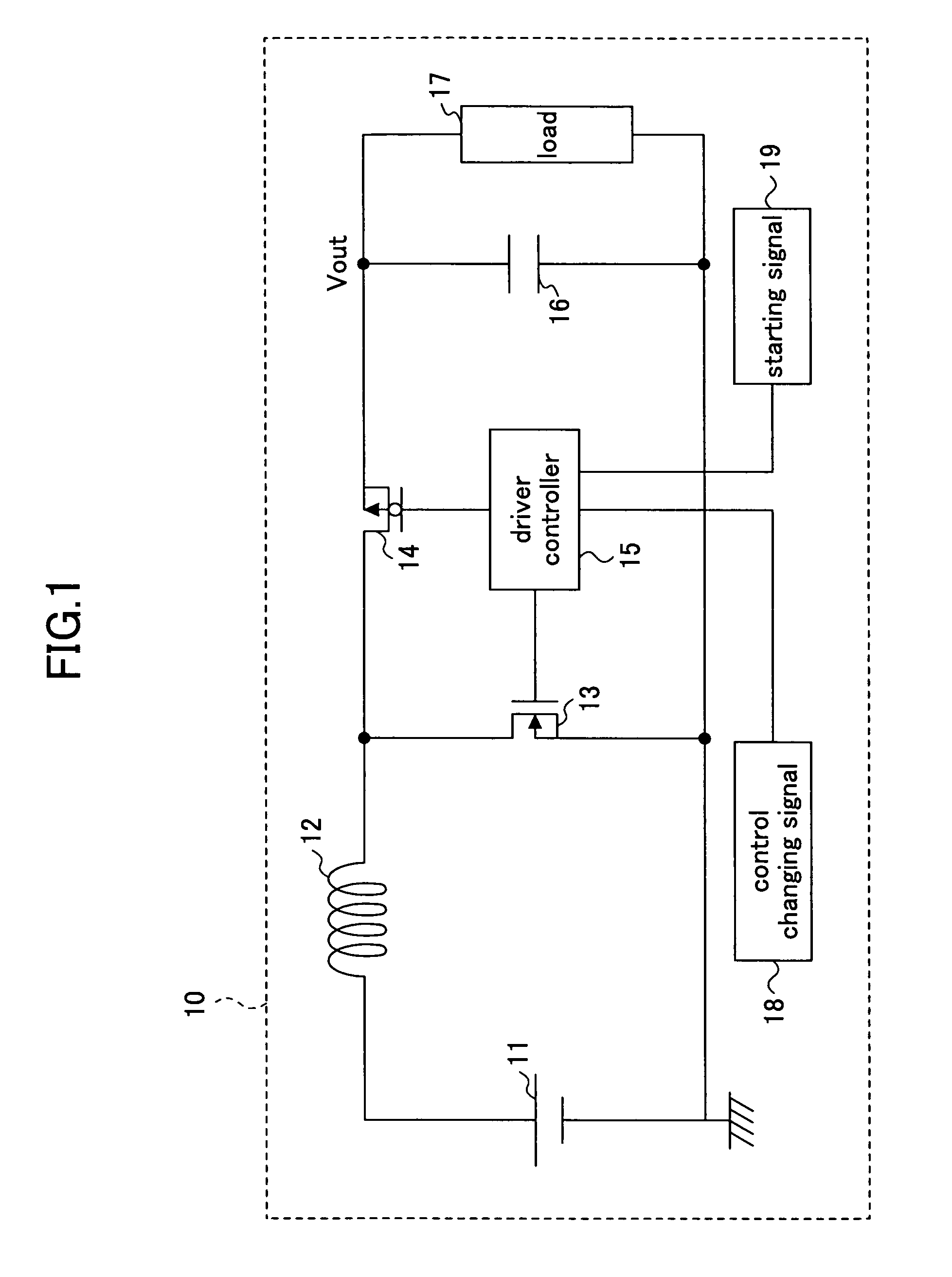
[0032]FIG. 1 is a circuit diagram illustrating a configuration of a step-up DC-DC converter according to the present invention.

[0033]As shown in FIG. 1, a step-up DC-DC converter 10 of the present embodiment includes an input power source 11, an inductor 12, a first switching element 13 formed of an NMOS transistor, a second switching element 14 formed of a PMOS transistor, a driver controller 15, an output smoothing capacitor 16, and a load 17.

[0034]In the step-up DC-DC converter 10, a positive polarity terminal of the input power source 11 is connected to an end of the inductor 12 in series, and a negative polarity terminal of the input power source 11 is connected to ground. The other end of the inductor 12 is connected to both the first switching element 13 and the second switching element 14. The first switching element 13 is connected to a negative polarity terminal of the input power source 11. The second switching element 14 is connected to the output smoothing capacitor 16 ...

second embodiment

[0045]the present invention is described below.

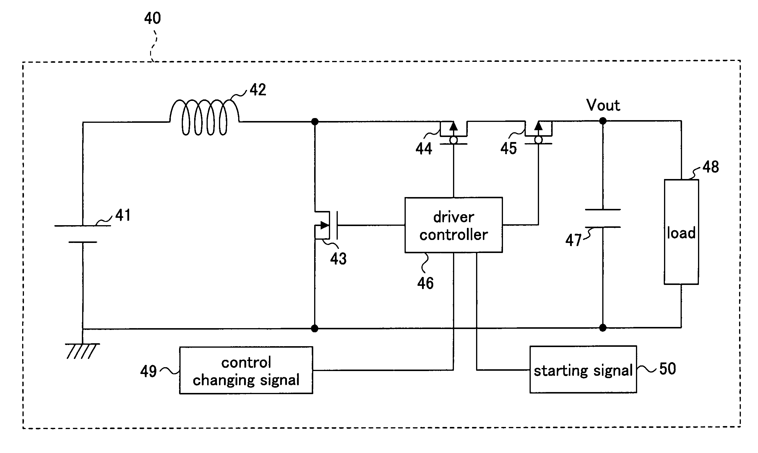
[0046]FIG. 3 is a circuit diagram illustrating a configuration of a step-up DC-DC converter according to a second embodiment of the present invention.

[0047]As shown in FIG. 3, a step-up DC-DC converter 40 of the present embodiment includes an input power source 41, an inductor 42, and a first switching element 43 formed of an NMOS transistor, two second switching elements 44, 45 connected in series and each formed of a PMOS transistor, a driver controller 46, an output smoothing capacitor 47, and a load 48.

[0048]In the step-up DC-DC converter 40 of the present embodiment, a positive polarity terminal of the input power source 41 is connected to an end of the inductor 42 in series, and a negative polarity terminal of the input power source 41 is connected to ground. The other end of the inductor 42 is connected to the first switching element 43 and the second switching elements 44, 45. The first switching element 43 is connected to a neg...


PUM


Abstract

A step-up DC-DC converter is disclosed that is capable of high efficiency power conversion under both a heavy load condition and a light load condition. The step-up DC-DC converter includes a direct current power source, an inductor, a first switching element, a second switching element, a smoothing capacitor, a driver controller for controlling switching ON or switching OFF the first switching element and the second switching element, and a control changing unit for changing a control operation of the driver controller according to a load current. According to an output from the control changing unit, the driver controller performs one of an operation of switching OFF the second switching element and an operation of switching ON or switching OFF the second switching element.

Description

BACKGROUND OF THE INVENTION[0001]1. Field of the Invention[0002]The present invention relates to a step-up DC-DC converter, and particularly, to a step-up DC-DC converter that synchronizes control operations of a first switching element and a second switching element, and supplies power at an input side to an output side.[0003]2. Description of the Related Art[0004]A frequently used method for a power device to convert an input voltage to a specified output voltage includes power conversion at high efficiency by using a switching DC-DC converter.[0005]The switching DC-DC converter controls a first switching element in synchronization with a second switching element, and this allows formation of channels in the switching elements, and thus, resistance of the switching elements in an ON state can be decreased, and high efficiency power conversion can be performed even under a heavy load. However, although high power conversion efficiency can be obtained under a heavy load, a charging ...

Claims


Application Information

Patent Timeline
Patent Type & Authority Patents(United States)
IPC IPC(8): G05F1/40
CPCH02M3/1588H02M2001/0032Y02B70/1466Y02B70/16H02M1/0032Y02B70/10
Inventor INOUE, YOSHIYUKI
Owner RICOH ELECTRONIC DEVICES CO LTD
Why Eureka
Try Eureka