Roofing bracket and system
a technology for roofs and brackets, applied in the direction of roofs, buildings, doors/windows, etc., can solve the problems of cumbersome and expensive process, more challenging and time-consuming aspects, and increase the cost of construction
- Summary
- Abstract
- Description
- Claims
- Application Information
AI Technical Summary
Benefits of technology
Problems solved by technology
Method used
Image
Examples
first embodiment
[0031]FIG. 3A is an exploded perspective view of a roofing bracket 100. Bracket 100 is comprised of two pieces, a clip 110 and a brace 120, coupled together with a rivet 115. The rivet forms a pivot point from which the two pieces (110 and 120) can be rotated about each other.
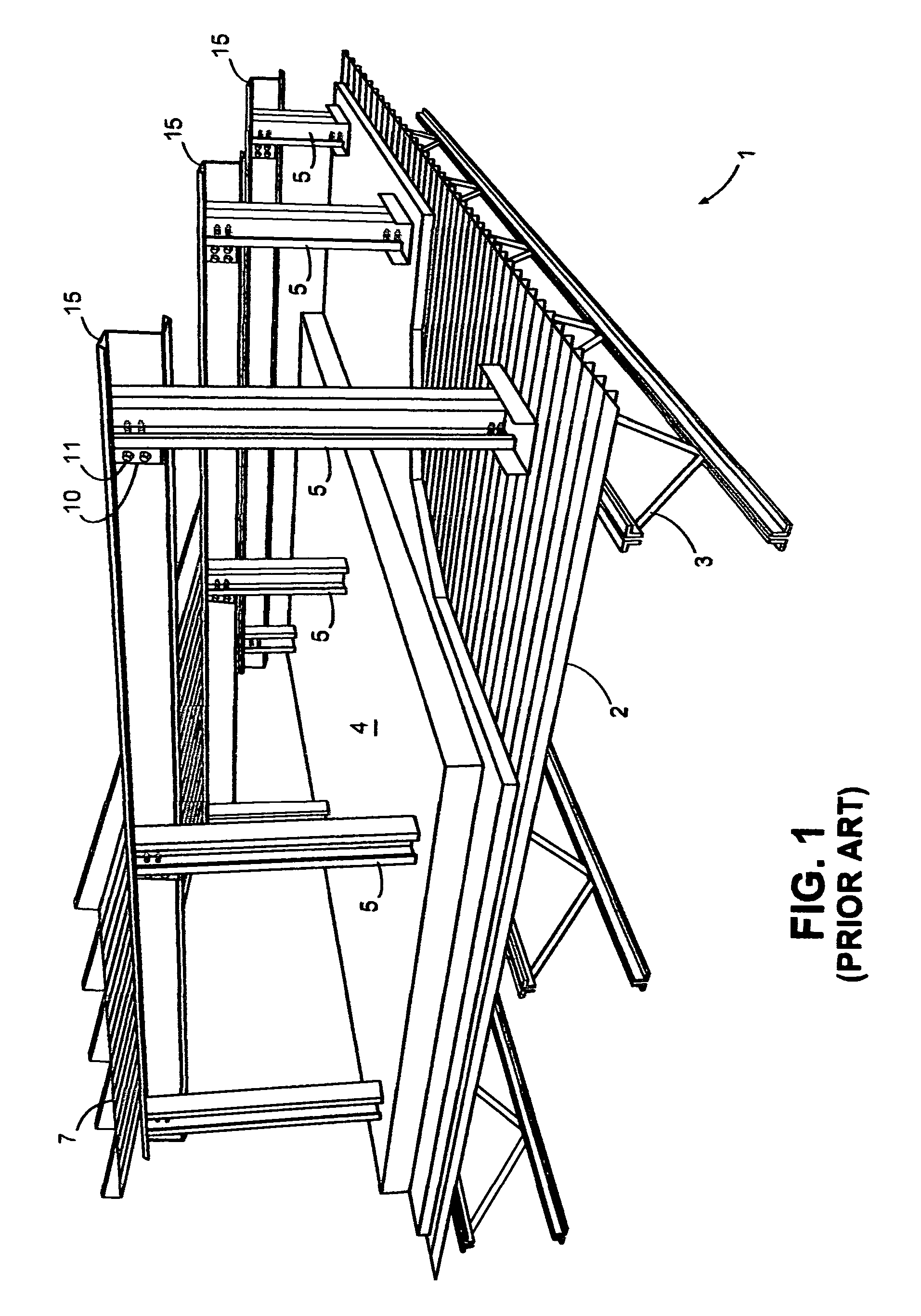
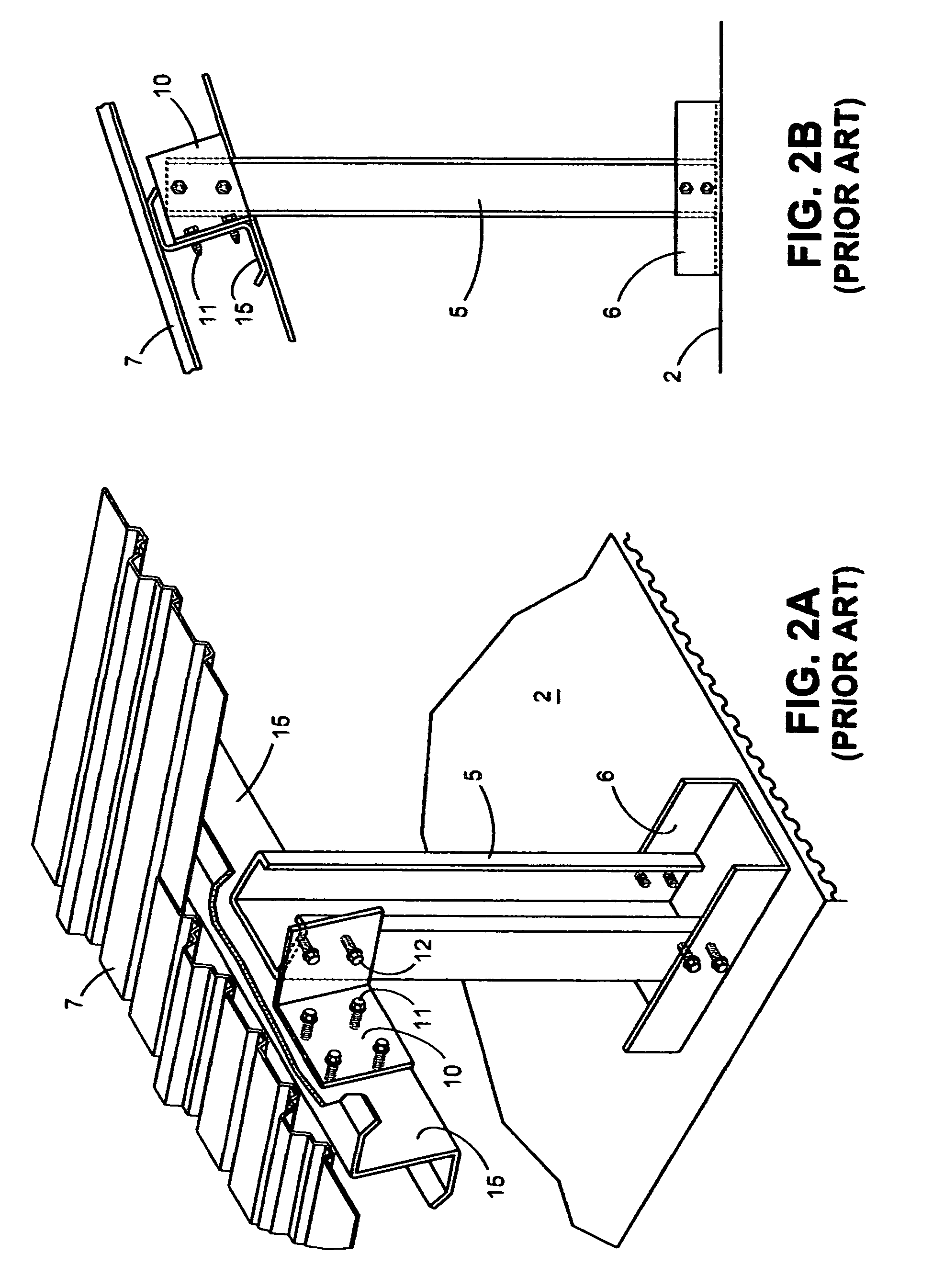
[0032]The clip 110 is comprised of two faces that meet at a common edge, forming a 90° angle. A first face 111 is designed to attach to the purlin 15 of the roofing system 1 (see FIGS. 1-2). The second face 112 is designed to attach to the vertical post 5, thus creating the coupling of the purlin 15 to the post 5.
[0033]The first face 111 may include preformed holes 119 for receiving fasteners 11. The first face 111 would preferably mount flush to the vertical face of a “Z” purlin and fastened thereto with fasteners 11. The specific location of the network of preformed holes 119 is beyond the scope of the present invention. Alternatively, no holes may be preformed in the face 111. The specific dimensions of the ...
second embodiment
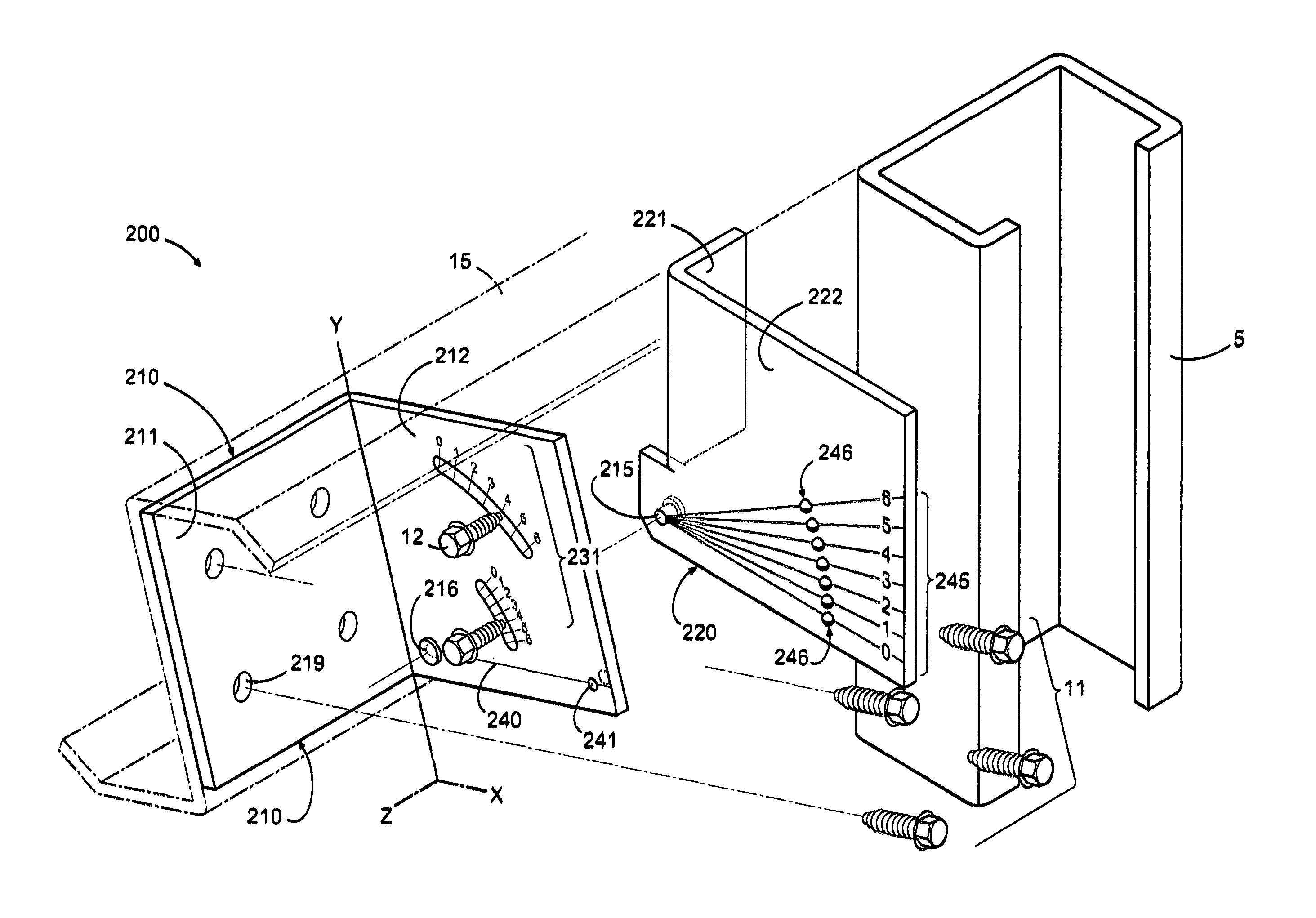
[0043]FIG. 4A-B illustrate a roofing bracket 200 according to the present invention. Similar to the roofing bracket 100 of FIGS. 3A-B, roofing bracket 200 comprises two pieces: a clip 210 and brace 220. Two variations are provides to distinguish this embodiment from the previous embodiment.
[0044]First, the preformed radial slit 130 of the clip 110 is replaced with stamped radial guides 231. In this case, the slit is not actually cut and removed from the metal. In this embodiment, self-puncturing fasteners would be required.
[0045]Second, the pivot point, and thus rivet 215 and rivet hole 216 has been positioned in the lower left corner, as opposed to centered about the bracket 200 in the Y direction. The reference marker 240 and angle reference guide 220 is thus positioned relative to the pivot point. The stamped radial guides 231 are also positioned relative to the placement of the pivot point.
[0046]In practice, the bracket 200 functions similarly to the bracket 100. The above descr...
third embodiment
[0047]FIGS. 5A-B illustrate a roofing bracket 300 in accordance with the present invention. This embodiment of the novel roofing bracket 300 is comprised of one single piece shaped to form three faces.
[0048]A first face 311 is positioned to mount flush with the vertical face of a purlin 15. As discussed with the other embodiments, the first face 310 may include a network of preformed holes 319 for receiving fasteners.
[0049]A second face 312 meets the first face 311 at a common edge to form, preferably, a 90° angle. The second face 312 is positioned to mount flush to a face of the vertical post 5. The second face 312 includes a stamped angle reference guide 345 and stamped radial fasteners guides 331. Alternatively, preformed radial slits for receiving fasteners could be incorporated.
[0050]A third face 313 is formed from a cutout of the first face 311 and meets the second face 312 at the common edge. The third face 313 is preferably formed at a 90° angle from the second face 312, thu...
PUM
 Abstract
Description
Claims
Application Information
 - R&D
- Intellectual Property
- Life Sciences
- Materials
- Tech Scout
- Unparalleled Data Quality
- Higher Quality Content
- 60% Fewer Hallucinations
Browse by: Latest US Patents, China's latest patents, Technical Efficacy Thesaurus, Application Domain, Technology Topic, Popular Technical Reports.
© 2025 PatSnap. All rights reserved.Legal|Privacy policy|Modern Slavery Act Transparency Statement|Sitemap|About US| Contact US: help@patsnap.com


