Method for apparatus for a drop indicator

a technology of drop indicator and drop indicator, which is applied in the direction of apparatus for force/torque/work measurement, analysis using chemical indicators, instruments, etc., can solve the problems of changing magnetic fields, affecting the detection accuracy of drop indicators, and unable to work out whether a product has ever been dropped or impacted, etc., to achieve the effect of facilitating observation

Active Publication Date: 2011-04-05
IND TECH RES INST +1
View PDF25 Cites 21 Cited by
  • Summary
  • Abstract
  • Description
  • Claims
  • Application Information

AI Technical Summary

Benefits of technology

[0010]The secondary goal of the invention is to allow examination of the condition of the consumptive electronic products. The invention, by being installed in the consumptive electronic products, helps decide whether a product has ever been dropped when in use, so that liabilities can be attributed to the manufacturer or the consumer.
[0011]To achieve the goals, the first embodiment of the drop indicator comprises a housing, a chamber, and at least one first seal element. The chamber is disposed inside the housing and has at least one first opening. The first seal element is used to seal the first opening. In this embodiment, the number of the opening determines the number of the seal element. For example, this embodiment comprises a second opening and a second element. The second opening and the first opening are disposed at the opposite ends of the hollow portion of the chamber. The chamber is filled with an indicative material, and the first seal element keeps the indicative material en-sealed in the chamber. In the event that the drop indicator is impacted, the first seal element and the indicative material will be released from the chamber and scattered inside the housing, helping determine whether a product has ever been impacted or dropped when in delivery. The indicative material comprises fluorescent powders or a plurality of colored granules, whose brightness facilitates observation.
[0014]The second embodiment of the present invention differs from the first embodiment in that the second embodiment allows impact detection in four directions, whereas the first embodiment allows impact detection in two directions. Namely, the second embodiment comprises a chamber having a first chamber and a second chamber formed in perpendicular to each other, with an indicative material filling each of the chambers. A first seal element, a second seal element, a third seal element, and a fourth seal element are used, respectively, to seal the first and the second openings of the first chamber and the third and the fourth openings of the second chamber to keep the indicative materials en-sealed en-sealed in the chambers. When the drop indicator is impacted or dropped, the magnetic element and the indicative material will be released from the chamber and scattered inside the housing, so as to indicate whether a product has ever been impacted or dropped either in delivery or in use.
[0028]This embodiment allows impact detection in multiple directions. Types of the chambers with five, or more than five, chambers can be provided if necessary, for purposes of allowing impact detection in multiple directions.

Problems solved by technology

Nonetheless, whenever the product is dropped accidentally or intentionally in delivery or under warranty, causing defects in the product without external damage or proof of damage, it is always the proprietor of business that is made liable for the defects and the subsequent warranty costs, which are never attributable to the consumer or whoever who really causes the accident.
Usually, it is very difficult to work out whether a product has ever been dropped or impacted during the period starting from the goods being packaged and delivered from the manufacturer to the end users to the discovery of defects in the product by end users upon opening the package.
The rotatable body will revolve when dropped or impacted, which will cause changes in the magnetic fields.
The string plate device comprises two spring plates, one of which will be disengaged when impacted or dropped, resulting in the break of circuit indicating that a shock or impact has occurred.

Method used


Image

  • Method for apparatus for a drop indicator
  • Method for apparatus for a drop indicator
  • Method for apparatus for a drop indicator

Examples


first embodiment

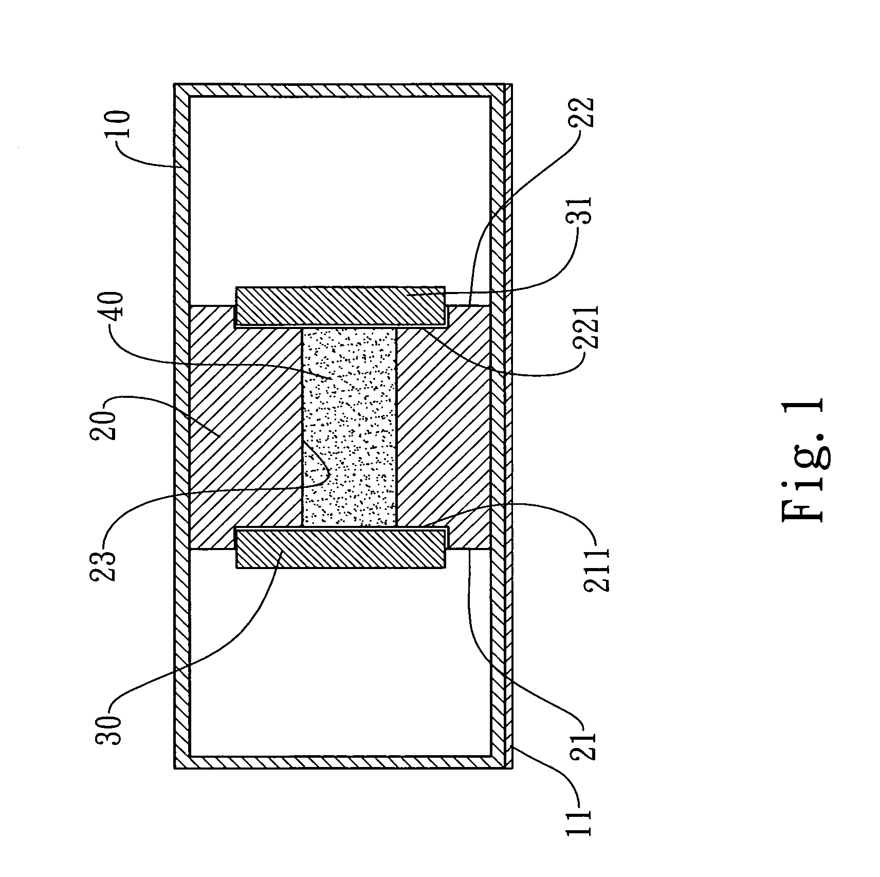
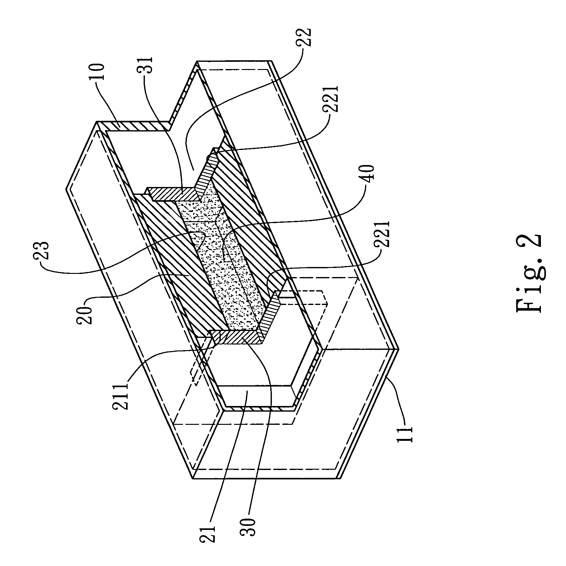
[0051]The invention further comprises a second opening 22 of the chamber 20, with a second seal element 31 placed upon the second opening 22 for closing the second opening 22. Therefore, the chamber 20 can have two openings, so as to allow impact detection in two directions.

[0052]The first opening 21 of the chamber 20 forms a first step portion 211 indented inwardly to allow the first seal element 30 to be mounted on the first step portion 211; the second opening 22 of the chamber 20 forms a second step portion 221 indented inwardly to allow the second seal element 31 to be mounted on the second step portion 221, so that the first seal element 30 and the second seal element 31 can be secured and not prone to shifting.

[0053]According to one type of the embodiment, both the first seal element 30 and the second seal element 31 are magnetic bodies. To attain the same magnetic effect as the preceding example does, the arrangements of the constituent materials among the first seal element...

second embodiment

[0060]In the present invention, the first opening 241, the second opening 242, the third opening 251, and the fourth opening 252 of the chamber 20 respectively form an inwardly indented first step portion 243, second step portion 244, third step portion 253, and fourth step portion 254, so as to allow the first seal element 30, the second seal element 31, the third seal element 32, and the fourth seal element 33 to be mounted on the first step portion 243, the second step portion 244, the third step portion 253, and the fourth step portion 254, respectively. That way, the first seal element 30, the second seal element 31, the third seal element 32, and the fourth seal element 33 can be secured and not prone to shifting.

[0061]According to one type of the embodiment, the first seal element 30, the second seal element 31, the third seal element 32, and the fourth seal element 33 can be magnetic bodies or metallic materials. To attain the same magnetic effect as the preceding example do...

third embodiment

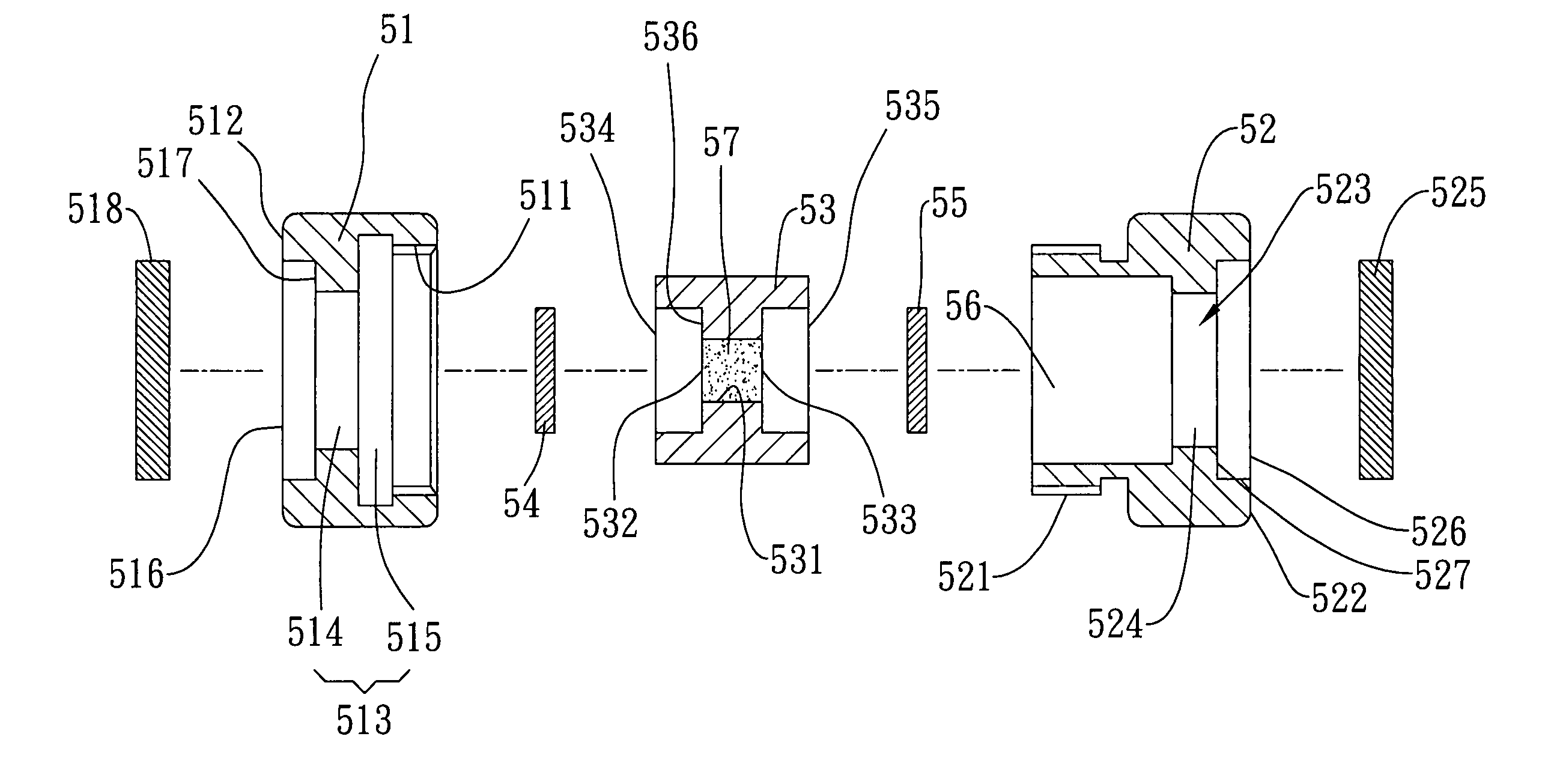
[0063]FIG. 4, FIG. 5, and FIG. 6 show an exploded view of the drop indicator, an exploded view of the sectioned drop indicator, and a sectional view of the assembled drop indicator, respectively, according to the present invention. In this embodiment, the drop indicator is circular in form, comprising a first element 51, a second element 52, a third element 53, a fifth seal element 54, and a sixth seal element 55, with the first element 51 and the second element 52 screwing each other forming a third space 56 containing the third element 53. The first element 51 comprises a hollow first joint portion 511 and a first outer end 512, the first joint portion 511 being next to a first space 513. The second element 52 comprises a hollow second joint portion 521 and a second outer end 522, the second joint portion 521 being next to a second space 523, allowing the first element 51 to join the second element 52 to form the third space 56 containing the third element 53. Since the first join...


PUM

PropertyMeasurementUnit
transparentaaaaaaaaaa
magneticaaaaaaaaaa
fluorescentaaaaaaaaaa

Abstract

The present invention relates to an apparatus and method for a drop indicator having a magnet installed therein. The drop indicator according to the invention is used to determine whether a product has ever been dropped or impacted, either in delivery or in use, by inspecting changes in the original condition of the magnet caused by the interaction between the magnetic force and the acceleration of gravity, inertia force, and colliding force, etc. generated upon collision. Take a cell phone or a PDA, for example, changes in the indicative material of the drop indicator will help decide whether the faulty product has ever been dropped or impacted in delivery or in use, so that liability can be determined.

Description

BACKGROUND OF THE INVENTION[0001]The present invention relates to an apparatus and method for a drop indicator, especially a drop indicator capable of telling whether a product has ever been impacted, either in delivery or in use, by showing changes in the indicative material of the drop indicator.[0002]In response to the market demand for compact, highly capable, and impressive-looking electronic products, product designers have made impact-related-damage prevention one of the necessary things to be considered when planning the design. The emphasis on impact-related-damage prevention has also become one of the most important gain items in the mechanical design of the products. To highlight the emphasis, the product designs are largely verified by simulated calculations and experimental results, through which repeated modifications of the mechanical design are made or additional shockproof materials are added in order to satisfy the desired specifications. Nonetheless, whenever the ...

Claims


Application Information

Patent Timeline
Patent Type & Authority Patents(United States)
IPC IPC(8): G01L5/00G01D11/00
CPCG01D7/005G01P1/127G01P15/18G01P15/038G01P15/06G01P15/036
Inventor PAN, SHEAU-SHICHANG, CHI-SHENGYANG, FENG-YU
Owner IND TECH RES INST
Why Eureka
Try Eureka