Frame coupling structure of windshield wiper

a frame coupling and wiper technology, applied in the field of frame coupling structure of windshield wipers, can solve the problems of poor coupling tightness, noise generation, time- and labor-intensive operation, etc., and achieve the effect of smooth wiping movement of the wiper, improved coupling tightness, and improved frame coupling structur

Inactive Publication Date: 2011-04-12
FU GANG CO LTD
View PDF4 Cites 39 Cited by
  • Summary
  • Abstract
  • Description
  • Claims
  • Application Information

AI Technical Summary

Benefits of technology

[0003]The primary object of the present invention is to provide a windshield wiper having an improved frame coupling structure that effectively improves the coupling tightness between primary and secondary frame members in assembling the wiper so that the wiping movement of the wiper is made smooth and the noise generated in the wiping operation of the wiper is eliminated.
[0004]The windshield wiper of the present invention comprises a primary frame member and secondary frame members coupled to the primary frame member. The primary frame member is in the form of an inverted U-shape and comprises end portions in which mounting holes are formed. Each secondary frame member comprises symmetrically arranged wall plates and a positioning section formed between the wall plates and slightly projecting beyond the wall plates. Each wall plate forms vertically extending open-ended slots that are symmetrically arranged. A boss is formed on an inside surface of each wall plate between the open-ended slots. The primary frame member comprises vertical side plates that are fit over the positioning section of the secondary frame member to have the wall plates of the secondary frame member covering and clamping the vertical side walls of the primary frame member. With the bosses fit into the mounting holes defined in the primary frame member, the coupling tightness between the primary and secondary frame members is improved whereby the wiping movement of the wiper is smooth and the noises generated during the wiping operation of the wiper are eliminated.

Problems solved by technology

This is time- and labor-consuming operation.
The windshield wiper so constructed has poor coupling tightness at the coupling points between the frame members, so that each time the wiper takes a wiping movement, noises are generated.

Method used


Image

  • Frame coupling structure of windshield wiper
  • Frame coupling structure of windshield wiper
  • Frame coupling structure of windshield wiper

Examples


Embodiment Construction

[0013]The following descriptions are exemplary embodiments only, and are not intended to limit the scope, applicability or configuration of the invention in any way. Rather, the following description provides a convenient illustration for implementing exemplary embodiments of the invention. Various changes to the described embodiments may be made in the function and arrangement of the elements described without departing from the scope of the invention as set forth in the appended claims.

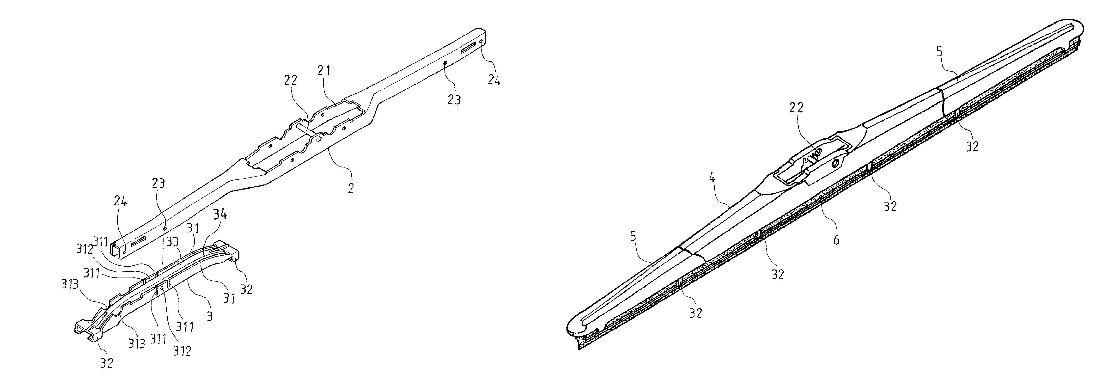
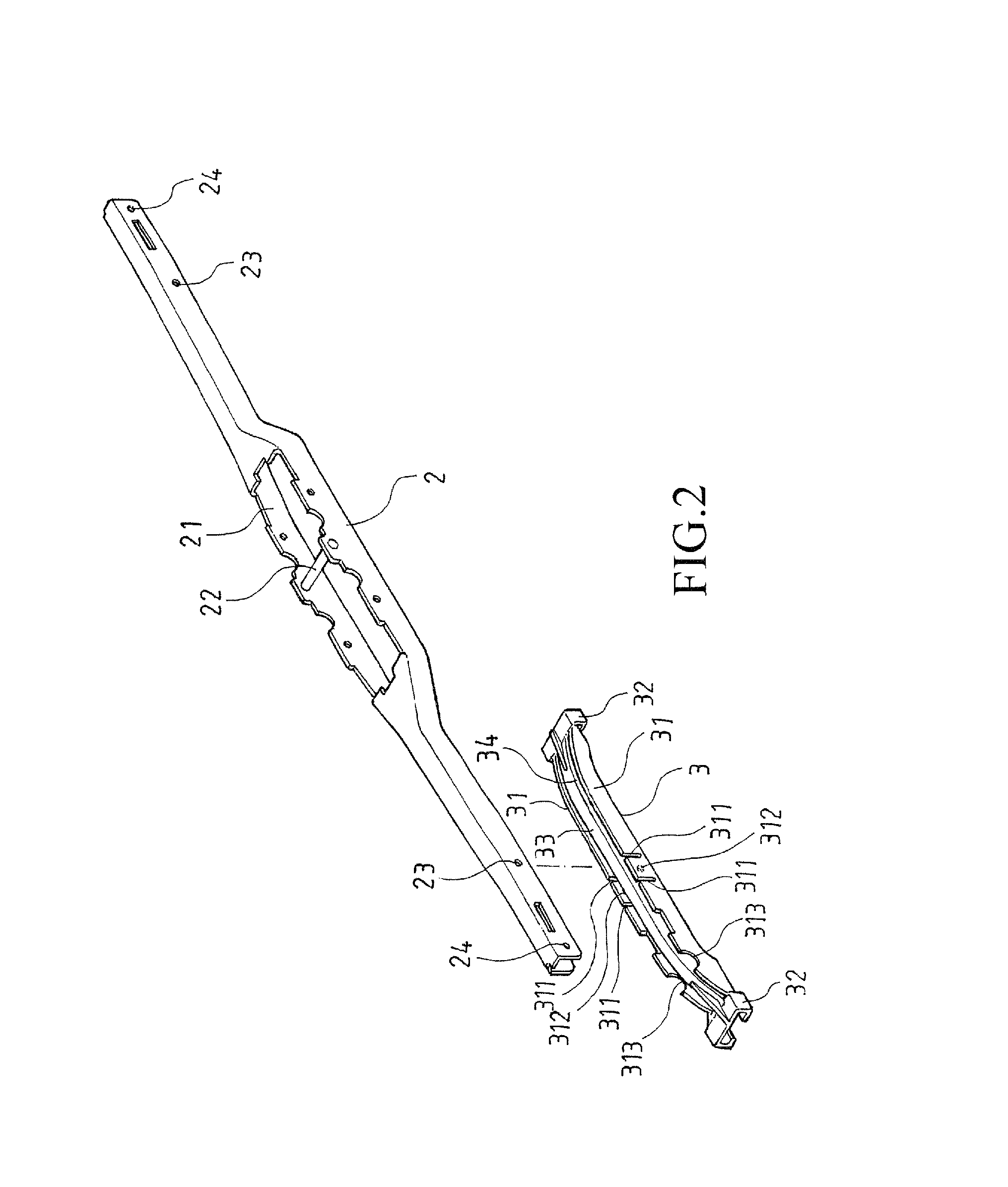
[0014]Referring to FIGS. 2 and 3, which are respectively an exploded view and a partial enlarged view of a windshield wiper constructed in accordance with the present invention, the windshield wiper of the present invention comprises a primary frame member 2 and secondary frame members 3 (only one being visible in FIG. 2) connected to the primary frame member 2. The primary frame member 2, which is in the form of an inverted U-shape, comprises a middle portion that forms an opening 21 in which a pos...


PUM


Abstract

A windshield wiper includes a primary frame member and secondary frame members coupled to the primary frame member. The primary frame member is in the form of an inverted U-shape and includes end portions in which mounting holes are formed. Each secondary frame member has symmetrically arranged wall plates and a positioning section formed between and slightly projecting beyond the wall plates. Each wall plate forms open-ended slots that are symmetrically arranged. A boss is formed on an inside surface of each wall plate between the open-ended slots. The primary frame member has side plates that are fit over the positioning section of the secondary frame member to have the wall plates of the secondary frame member covering and clamping the vertical side walls of the primary frame member. The bosses are fit into the mounting holes of the primary frame member.

Description

(a) TECHNICAL FIELD OF THE INVENTION[0001]The present invention generally relates to a frame coupling structure of windshield wiper, and more particularly to a frame coupling structure of windshield wiper that improves coupling tightness between primary and secondary frame members, making the wiping operation of the wiper smooth and thus eliminating the noises generated by the wiping operation of the wiper.(b) DESCRIPTION OF THE PRIOR ART[0002]A known windshield has a construction shown in FIG. 1 of the attached drawings, comprising a major frame member 11, two intermediate frame members 12 coupled to the major frame member 11, and four minor frame members 13 coupled to the intermediate frame members and a rubber blade 14 attached to pawls formed on the frame members. The major frame member 11 forms in a central portion thereof a coupling section 111 that is coupled to a wiper arm of an automobile for driving the reciprocal wiping movement of the wiper. Such a known wiper structure ...

Claims


Application Information

Patent Timeline
Patent Type & Authority Patents(United States)
IPC IPC(8): B60S1/38
CPCB60S1/3801B60S2001/3815
Inventor CHIANG, MIN-HENG
Owner FU GANG CO LTD
Why Eureka
Try Eureka