
Apparatus for mounting a solar panel or other article to a roof or other structure

a technology for solar panels and other objects, which is applied in the direction of light and heating apparatus, snow traps, heat collector mounting/support, etc., can solve the problems of increasing the likelihood of leakage, premature roof deterioration, and difficulty in installing solar panels or other objects to the roof of buildings, so as to preserve the roof

Inactive Publication Date: 2011-04-12
THOMPSON TECH IND
View PDF22 Cites 53 Cited by
  • Summary
  • Abstract
  • Description
  • Claims
  • Application Information

AI Technical Summary

Benefits of technology

"The present invention provides an apparatus for mounting solar panels and other articles to roofs and structures that is self-contained, waterproof, and easy to install. The apparatus includes a base plate, threaded stud, lag bolts, spacer, and flashing. The spacer acts as a lift for mounting an article up off the roof, while the flashing prevents water from penetrating the structure. The apparatus is low-profile, requires no exterior sealants, and provides a lifetime UV resistant surface. The invention also provides a waterproof method of mounting objects to roofs and structures with minimal labor and materials. The apparatus can be used for solar panels, solar water panels, AC units, TV antennas, satellites, guide wire supports, or other articles. The invention is particularly useful in extreme environments."

Problems solved by technology

Installing a solar panel or other article to the roof of a building can be problematic.
In addition, securing the article too close to the roof may obstruct proper drainage and create a water dam, thereby increasing the likelihood of leakage and premature roof deterioration.

Method used


Image

  • Apparatus for mounting a solar panel or other article to a roof or other structure
  • Apparatus for mounting a solar panel or other article to a roof or other structure
  • Apparatus for mounting a solar panel or other article to a roof or other structure

Examples


Embodiment Construction

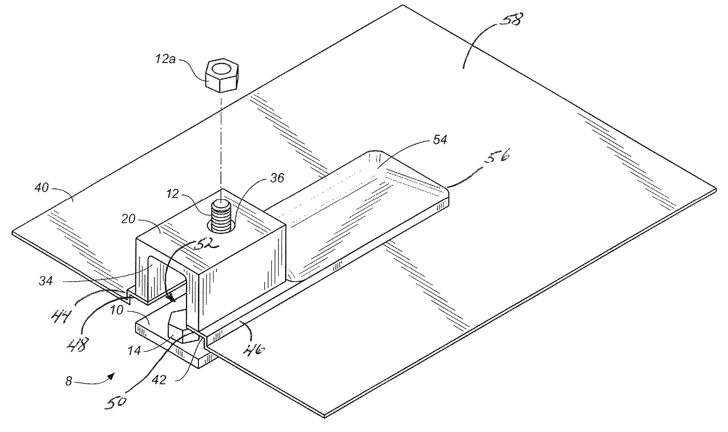
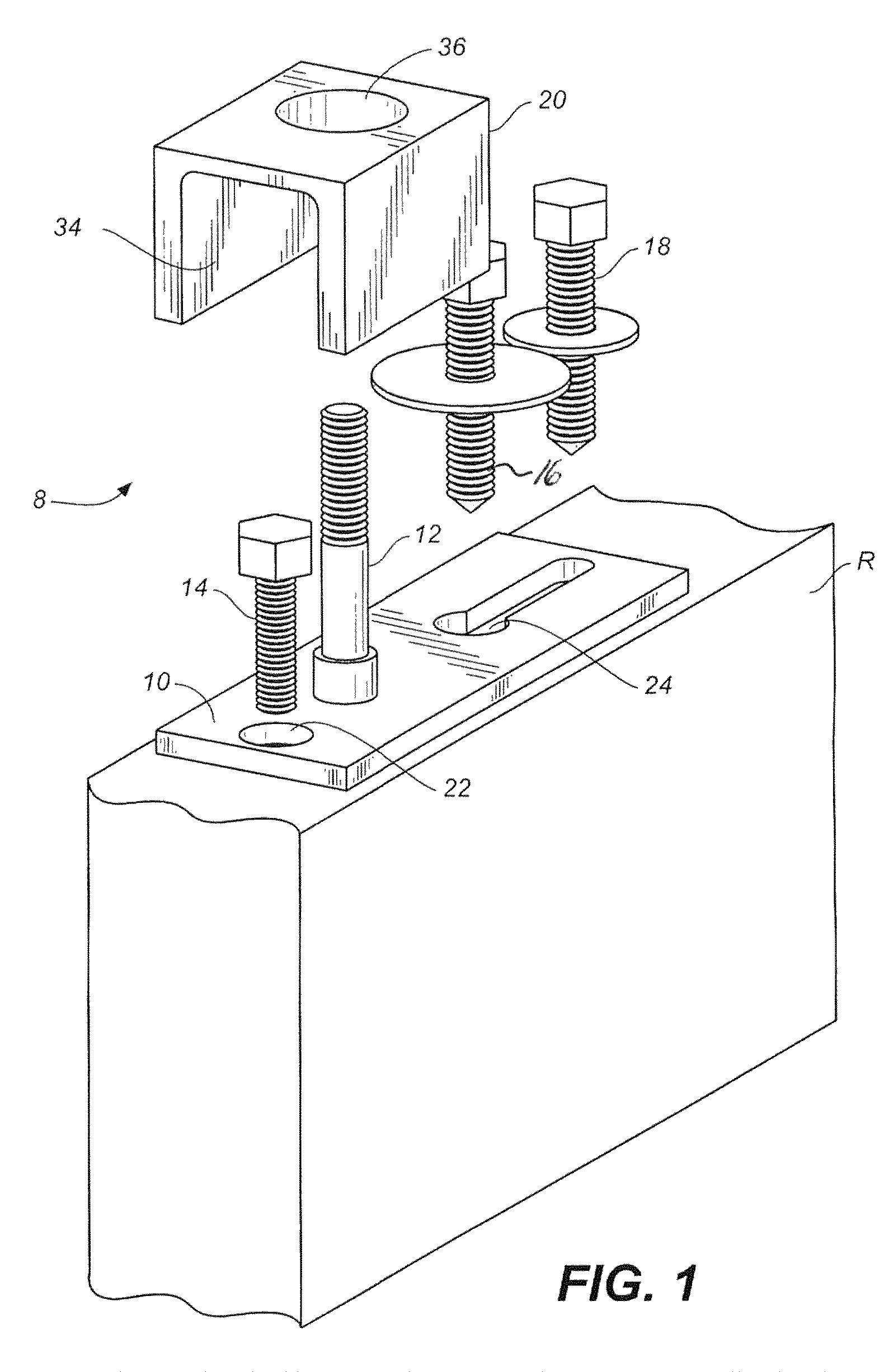
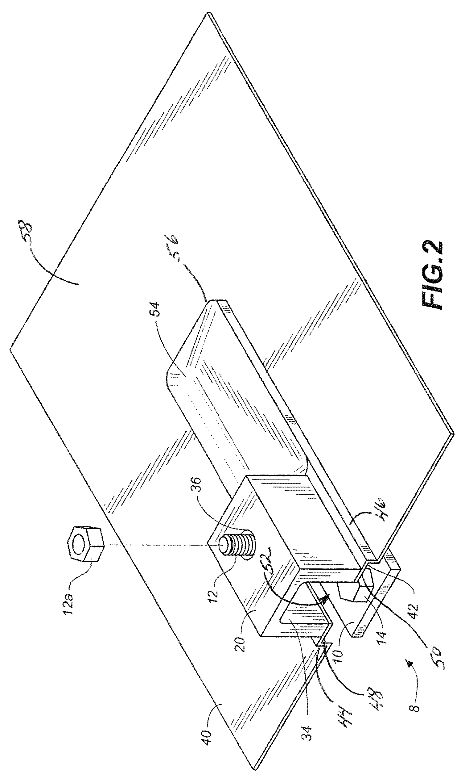
[0019]Referring to FIGS. 1 and 2, wherein like reference numerals refer to like components in the respective views, there is illustrated therein a new and improved apparatus for mounting a solar panel or other article to a roof or other structure, generally denominated 8 herein.

[0020]FIG. 1 is a perspective view of the essential structural elements of the inventive apparatus, including an elongate base plate 10, a threaded stud 12 integral with or welded to the base plate and extending upwardly therefrom, lag bolts 14, 16, 18 and spacer 20. These elements are shown adjacent a roof truss or other structure 22. Base plate 10 is preferably constructed of stainless steel or similar material and is generally elongate, measuring in the preferred embodiment 1.63 inches wide×5.1 inches long. Base plate 10 includes bolt holes 22, 24 to accommodate lag bolts 14, 16, 18. Bolt hole 24 is preferably keyhole-shaped to enable adjustment of the base plate during installation. The base plate further...


PUM


Abstract

An apparatus for mounting an article to a roof includes a base plate, threaded stud, lag bolts, spacer, and flashing. The base plate includes bolt holes to accommodate the lag bolts to secure the base plate to the roof. The threaded stud is secured to and extends vertically from the base plate. The spacer is inserted over the stud so that the stud passes through an aperture in the spacer, and is secured by a nut. The spacer acts as a lift for mounting an article up off the roof, thereby permitting drainage. The spacer includes a recess to accommodate the head of a lag bolt. The wrap-around flashing is captured between the base plate and spacer, creating a water free environment underneath the assembled unit. The flashing slides up underneath the roofing shingles to prevent water from penetrating the structure, and includes a lip to accommodate the base plate, and a detent to accommodate the bolt heads beneath it.

Description

CROSS REFERENCE TO RELATED APPLICATIONS[0001]The present application is a continuation-in-part patent application of U.S. patent application Ser. No. 11 / 326,271, filed Jan. 4, 2006, which application claims the benefit of the filing date of U.S. Provisional Patent Application Ser. No. 60 / 641,198, filed Jan. 4, 2005.STATEMENT REGARDING FEDERALLY SPONSORED RESEARCH OR DEVELOPMENT[0002]Not applicable.REFERENCE TO A MICROFICHE APPENDIX[0003]Not applicable.TECHNICAL FIELD[0004]The present invention relates generally to construction materials and mounting hardware, and more particularly to an improved apparatus for mounting a solar panel or other article to a roof or other structure.BACKGROUND INFORMATION AND DISCUSSION OF RELATED ART[0005]Installing a solar panel or other article to the roof of a building can be problematic. For example, simply bolting the article to the building's roof trusses may create an entry point for precipitation. In addition, securing the article too close to th...

Claims


Application Information

Patent Timeline
Patent Type & Authority Patents(United States)
IPC IPC(8): E04D1/36
CPCF24J2/5245H02S20/23F24J2002/4669Y02B10/20Y02E10/47Y02B10/12F24S25/61F24S2025/6006Y02E10/50Y02B10/10
Inventor THOMPSON, DANIEL S.MULLINS, MONTYPROCTOR, RICHARD I.ZHANG, ZHAN
Owner THOMPSON TECH IND
Learn More