Soundproof assembly and methods for manufacturing same

Active Publication Date: 2011-04-12
PACIFIC COAST BUILDING PRODS
View PDF107 Cites 49 Cited by
  • Summary
  • Abstract
  • Description
  • Claims
  • Application Information

AI Technical Summary

Benefits of technology

[0008]A structure in accordance with the present invention significantly simplifies the construction of a floor/ceiling structure and in addition significantly reduces sound transmission from adjacent living spaces. In the embodiment described, the structu

Problems solved by technology

Noise is emerging as both an economic and public policy issue.
To the detriment of the U.S. economy, both problems have resulted in major builders refusing to build homes, condos and apartments in certain municipalities; and in widespread cancellation of liability insurance for builders.
Unfortunately, even the best of such walls using standard drywall are capable of only reducing sound transmission by approximately 30 db, and much of that is focused on mid-range and high frequencies rather than lower frequencies which cause most of the complaints and litigation.
A brief review of commercial

Method used


Image

  • Soundproof assembly and methods for manufacturing same
  • Soundproof assembly and methods for manufacturing same
  • Soundproof assembly and methods for manufacturing same

Examples


Embodiment Construction

[0028]The following detailed description is meant to be exemplary only and not limiting. Other embodiments of this invention, such as the number, type, thickness and placement order of both external and internal layer materials, will be obvious to those skilled in the art in view of this description.

[0029]The process for creating such laminar panels takes into account many factors: exact chemical composition of the glue; various symmetric and non-symmetric thicknesses of glue and layered material; pressing process; drying and dehumidification process.

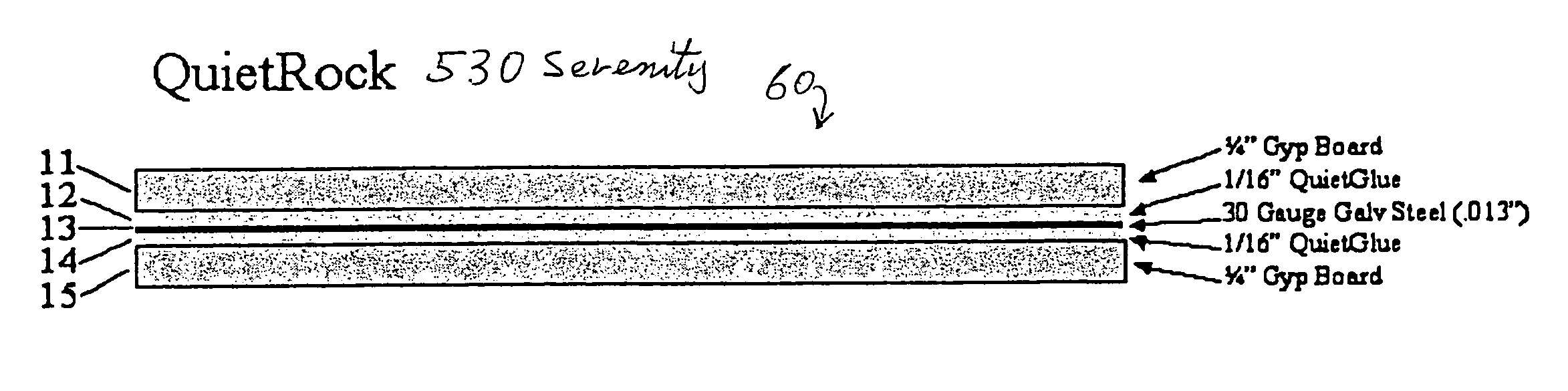
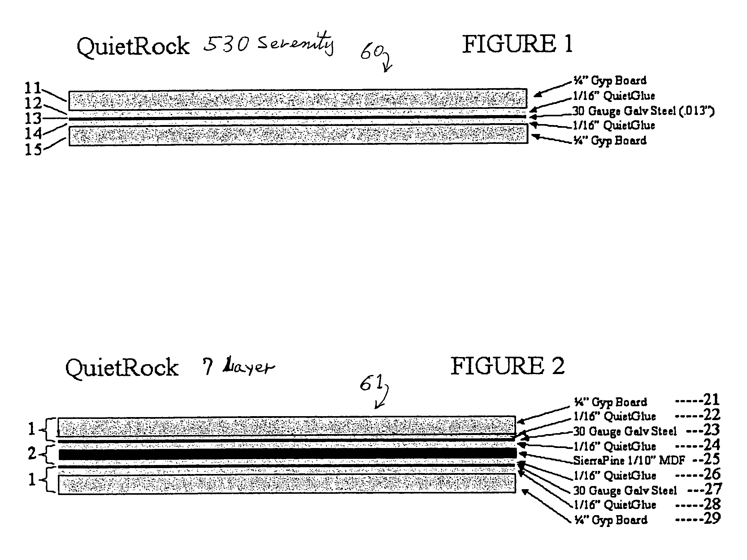
[0030]FIG. 1 shows a laminar panel 60. In FIG. 1, the layers in the structure will be described from top to bottom with the structure oriented horizontally as shown. It should be understood, however, that laminar panel 60 will be oriented vertically when placed on vertical walls and doors, as well as horizontally or even at an angle when placed on ceilings and floors. Therefore, the reference to top and bottom layers is to be understood...


PUM

PropertyMeasurementUnit
Fractionaaaaaaaaaa
Fractionaaaaaaaaaa
Thicknessaaaaaaaaaa

Abstract

An improved acoustical floor/ceiling, or wall assembly affixed to a support structure, the assembly using laminar panels. A first one of the laminar panels includes a constraining layer of material with a layer viscoelastic glue on the constraining layer and a layer of material of a first composition on the layer of viscoelastic glue. A second one of the laminar panels includes a constraining layer of material with a layer of viscoelastic glue on the constraining layer of material and a layer of material of a composition different than that of the layer of material in the other laminar panel. In one assembly the material in the first laminar panel is cellulose-based material or wood, and the material in the second laminar panel is gypsum board. Constraining layers of material of metal, cellulose-based material, wood and petroleum-based products such as plastic, vinyl or rubber, ceramic, composite are employed.

Description

CROSS REFERENCE TO RELATED APPLICATION(S)[0001]This application is related to commonly assigned U.S. patent application Ser. No. 10 / 658,814 filed Sep. 8, 2003, by Kevin J. Surace and Marc U. Porat, entitled “Accoustical Sound Proofing Material and Methods for Manufacturing Same”, and U.S. patent application Ser. No. 10 / 938,051 filed Sep. 10, 2004, by Kevin J. Surace and Marc U. Porat, entitled “Acoustical Sound Proofing Material and Methods for Manufacturing Same,” both of which are incorporated by reference herein in their entirety.FIELD OF THE INVENTION[0002]This invention relates to acoustical damping materials and, in particular, to soundproofing materials of a novel laminar construction which significantly improves the soundproofing ability of walls, ceilings, floors, and doors, thereby to prevent the transmission of sounds from one area to another.BACKGROUND OF THE INVENTION[0003]Noise is emerging as both an economic and public policy issue. Soundproof rooms are required for a...

Claims


Application Information

Patent Timeline
IPC IPC(8): E04B1/82
CPCB32B7/12B32B13/06B32B15/08E04B5/10E04B5/12E04B9/045E04B1/86E04B2001/8461
Inventor SURACE, KEVIN J.
Owner PACIFIC COAST BUILDING PRODS
Why Eureka
Try Eureka