
Ball marker for golf

a golf marker and ball marker technology, applied in the field of golf ball markers, can solve the problem that golfers cannot satisfactorily grasp and achieve the effect of easy portability and easy recognition of the position of the ball marker

Inactive Publication Date: 2011-04-12
LIM CO LTD
View PDF13 Cites 12 Cited by
  • Summary
  • Abstract
  • Description
  • Claims
  • Application Information

AI Technical Summary

Benefits of technology

"The present invention provides a golf ball marker that can easily be recognized by golfers and adjusted to provide different levels of position indication. The marker is made up of a round-shaped case, a thin film printed circuit board with a light-emitting diode flickering control chip, and a flexible printed circuit cable with surface mounted device light emission diodes. The marker also includes a transparent rubber layer, an electric cell, a button switch, and a lower fixing portion fused with soft resin. The invention also provides a ball marker with a solar cell part and a switch button laminated on the top surface of the thin film printed circuit board, as well as a transparent layer hardened and formed on the thin film printed circuit board in such a way that the switch button is exposed to the outside. The ball marker is easy to carry and can be transformed into other type ball markers as occasion demands."

Problems solved by technology

Furthermore, the golfer cannot sometimes satisfactorily grasp the position of the ball marker due to excessively strong sunshine or feels difficulty to find the ball marker in a cloudy weather, at dawn, at night, or under night illumination.

Method used


Image

  • Ball marker for golf
  • Ball marker for golf
  • Ball marker for golf

Examples


Embodiment Construction

[0023]Reference will be now made in detail to the preferred embodiment of the present invention with reference to the attached drawings.

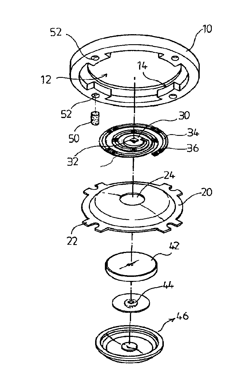
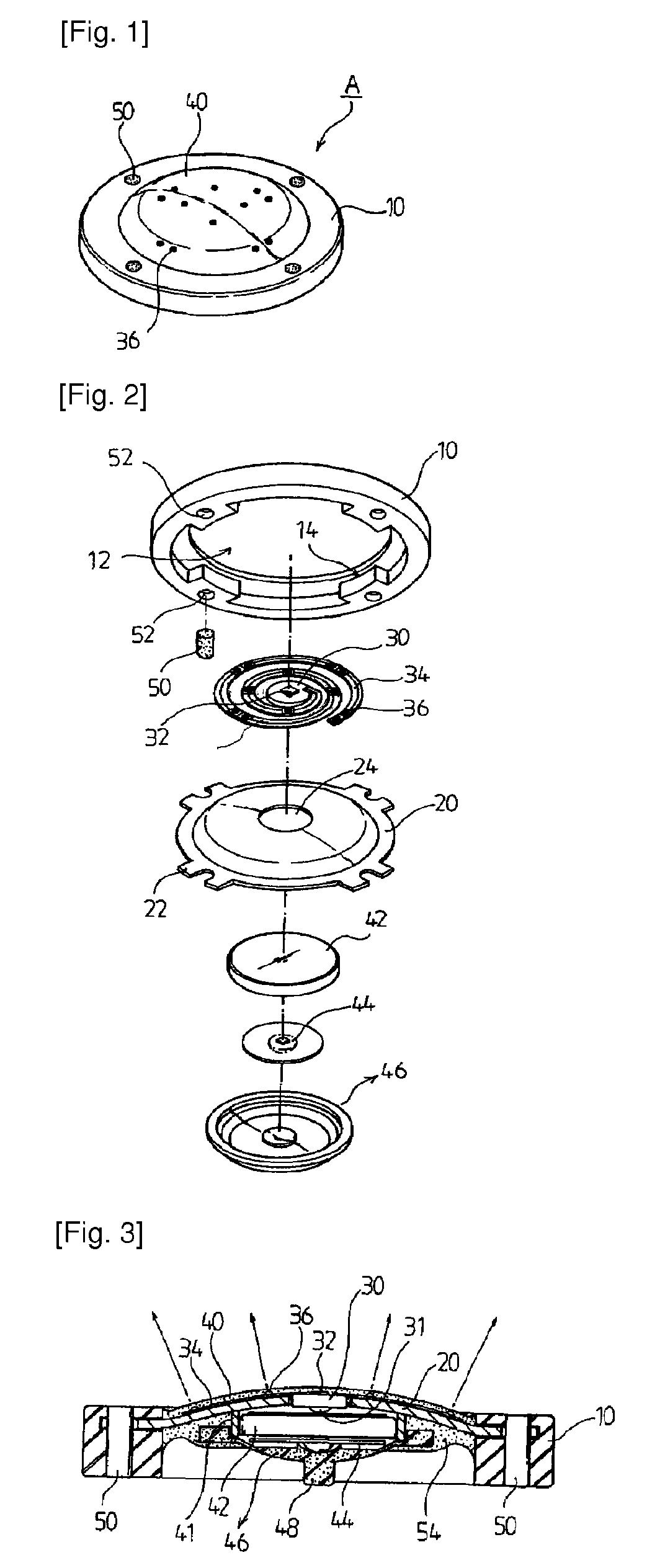
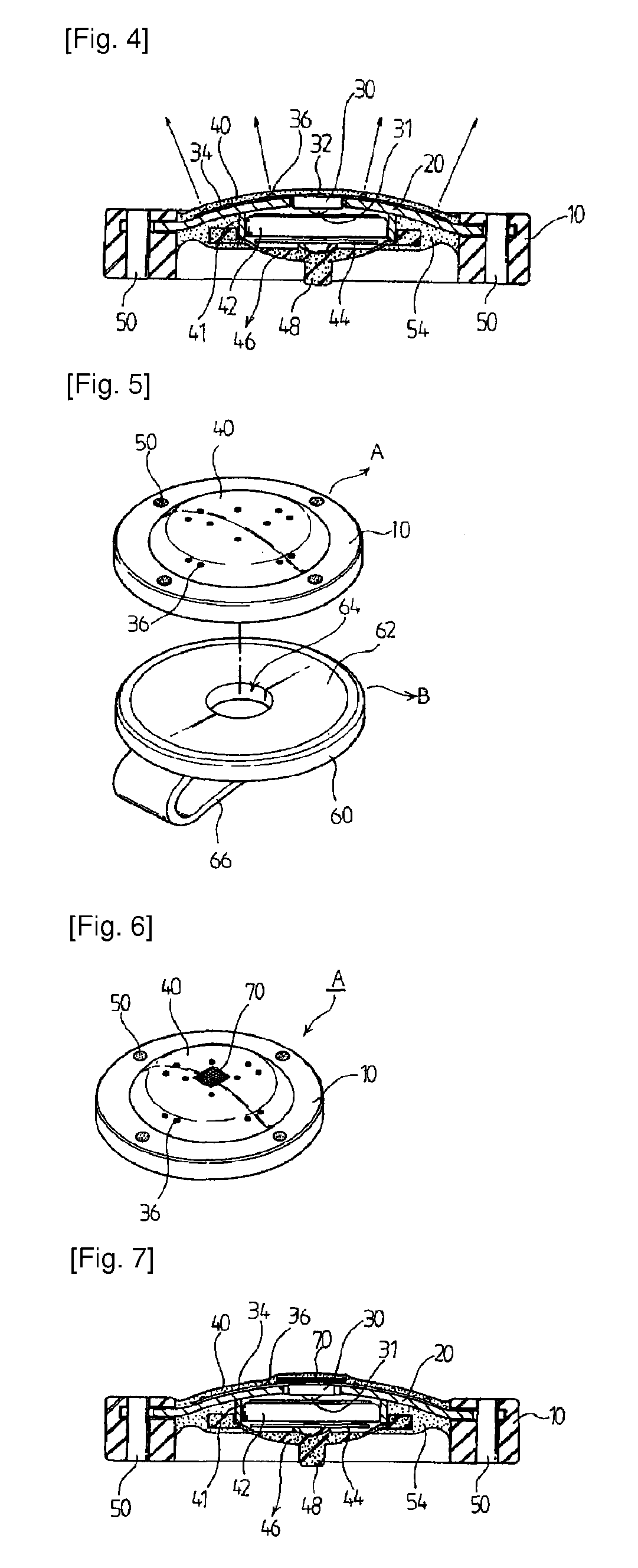
[0024]FIG. 1 is a perspective view of a ball marker for golf according to a first preferred embodiment of the present invention, FIG. 2 is an exploded perspective view of FIG. 1, FIGS. 3 and 4 are sectional views showing a used state of the ball marker for golf according to the present invention, and FIG. 5 is an exploded perspective view showing a state where the ball marker for golf according to the present invention is attached to a clip coupler.

[0025]First, referring to FIGS. 1 and 2, a ball marker (A) for golf according to a first preferred embodiment of the present invention has a diameter equal to or larger than a general coin size, and includes a round-shaped case 10 made of a synthetic resin material and having an opening 12. An uneven portion is formed on the bottom portion of the opening 12 of the round-shaped case 10, so that the disc sp...


PUM


Abstract

Provided is a ball marker for golf, including: a round-shaped case having an opening; a disc spring fit to the round-shaped case; a thin film printed circuit board and a flexible printed circuit cable seated on a top surface of the disc spring, the thin film printed circuit board having a light-emitting diode flickering control chip, the flexible printed circuit cable being connected to the thin film printed circuit board and having a plurality of surface mounted device light emission diodes; a transparent rubber layer formed on the thin film printed circuit board and the flexible printed circuit cable; an electric cell received in a receiving portion of the disc spring exposed from a lower portion of the round-shaped case; a button switch and a button cover arranged on the electric cell; and a lower fixing portion fused and fixed with soft resin.

Description

CROSS-REFERENCE TO RELATED APPLICATIONS[0001]The present application is a continuation application of PCT / KR2008 / 004892 filed on Aug. 21, 2008 which claims priority from Korean Patent Application No. 2007-0085607 filed on Aug. 24, 2007 and Korean Patent Application No. 2007-0126528 filed on Dec. 7, 2007, which are incorporated herein by reference in the entirety.BACKGROUND ART[0002]The present invention relates to an improve ball marker for golf.[0003]In general, while golfers can putt a ball to a distance of 200 meter to 300 meter in one stroke, they have a number of examples that they cannot make a hole-in-one even at a distance shorter than 1 meter on a putting green. The putting green is the only area where the golfer can directly pick up, touch and wash the ball with the hand on his or her golf game. Since putting on the putting green requires sensitiveness, high delicacy and high power of concentration, the golfer can put a mark of the ball directly behind the ball (position f...

Claims


Application Information

Patent Timeline
Patent Type & Authority Patents(United States)
IPC IPC(8): A63B57/00A63B102/32A63B57/35
CPCA63B57/0075A63B2225/54A63B2209/08A63B2207/02A63B57/207A63B57/353A63B2225/74H05K1/147A63B2225/76
Inventor LIM
Owner LIM CO LTD
Learn More