Method for controlling battery pack

a battery pack and control method technology, applied in the direction of electric vehicles, circuit monitoring/indication, transportation and packaging, etc., can solve the problems of abnormality in the charge control switch, battery pack or electronic equipment using it being subjected to this type of influence of noise, and the current value is occasionally detected, so as to reduce the adverse influence of the battery pack, and quickly stop charging the battery pack.

Active Publication Date: 2011-04-12
PANASONIC ENERGY CO LTD
View PDF11 Cites 21 Cited by
  • Summary
  • Abstract
  • Description
  • Claims
  • Application Information

AI Technical Summary

Benefits of technology

[0006]The present invention is aimed at solving the above problem, and its object is to provide a method for controlling a battery pack that more appropriately and accurately determines abnormality of a charge control switch.
[0008]In the aforementioned control method, it is determined that abnormality occurs if it is detected that the current flows at a rate not less than the first current value during the first detection period, for example, it is determined that abnormality occurs if it is detected that a large amount of current not less than the first current value flows during the first detection period shorter than the second detection period. Therefore, since a large current flow can be detected in a short period, it is possible reduce an adverse influence on the battery. In other words, it is possible to quickly stop charging a battery pack in an abnormal state, and to quickly stop charging a highly abnormal battery.

Problems solved by technology

However, even in disconnection control operation, if a battery pack or electronic equipment using it is under the influence of noise, such a current value is occasionally detected.
In this case, it may be falsely determined that abnormality occurs in the charge control switch.
Particularly, a battery pack or electronic equipment using it tends to be subjected to this type of influence of noise when electronic devices such as mobile phone that generate radio wave are used near the battery pack or electronic equipment.
However, in the case where the preset value is set to a large value, there is a problem that cannot determine an abnormal state where a small amount of current flows.

Method used


Image

  • Method for controlling battery pack
  • Method for controlling battery pack
  • Method for controlling battery pack

Examples


Embodiment Construction

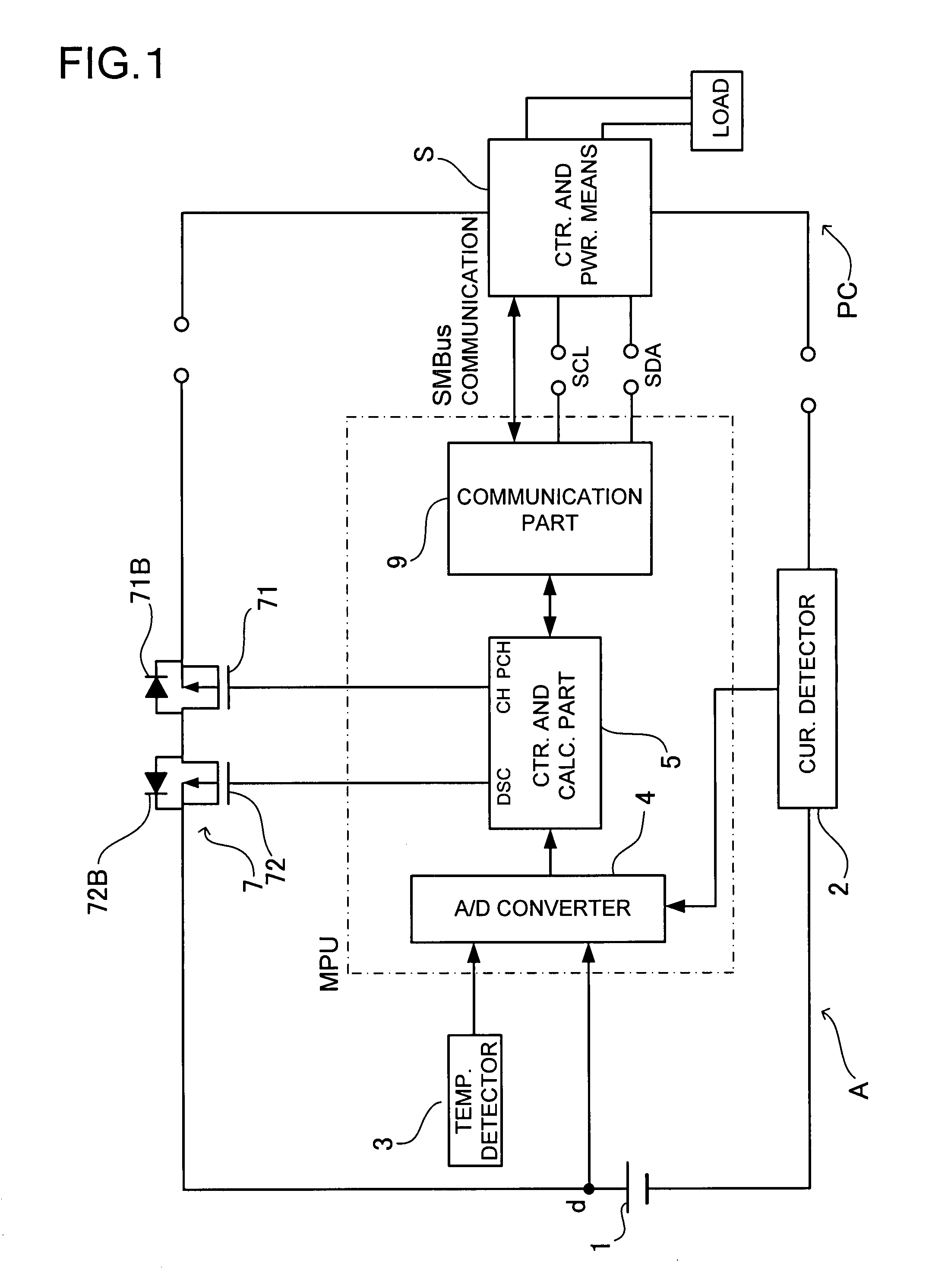
[0016]An embodiment of the present invention will be described with reference to drawings. As shown in FIG. 1, a battery pack A, and a mobile device PC as electronic equipment with a power source, which charges the battery pack A, are provided in this embodiment. The mobile device PC is a mobile personal computer such as note type personal computer. Typically, the battery pack A has structure that can be detachably attached to the mobile device PC. The mobile device PC includes control-and-power means S. The control-and-power means S is provided with direct-current power, which is provided from an adaptor (not shown). The adaptor converts commercial alternating-current power through a wall outlet into the direct-current power. The control-and-power means S includes a microcomputer, which controls this power for power supply. The power supply from the control-and-power means S is used to charge the battery pack A or is provided to a load L of the mobile PC. On the other hand, when po...


PUM


Abstract

A method controls a battery pack that includes a rechargeable battery, a control circuit that controls charge operation of the battery, and a charge control element that controls the charge current through the control circuit. In the method, even though the control circuit controls the charge control element so that the charge control element turns to OFF, in a case where the charge current is detected, the control circuit determines that abnormality occurs if detecting that the current flows at a rate not less than a first current value during a first detection period, and additionally determines that abnormality occurs if detecting a state the current flows at a rate less than the first current value for a second detection period longer than the first detection period.

Description

BACKGROUND OF THE INVENTION[0001]1. Field of the Invention[0002]The present invention relates a method for controlling a battery pack.[0003]2. Description of the Related Art[0004]Japanese Laid-Open Publication KOKAI No. HEI 9-261883 discloses various types of battery abnormality detection, which detect states where rechargeable batteries cannot be properly used due to deterioration of the rechargeable batteries, large property variation between them, a short circuit in any of them, or the like. If such states are detected, charge operation (or discharge operation) is stopped. Specifically, the various types of detection includes the steps of detecting battery voltage of a rechargeable battery in charge operation, comparing the detected battery voltage with a preset voltage value, and stopping charging the rechargeable battery if the detected battery voltage is not less than the preset voltage value for longer than a preset period. In addition, as disclosed in paragraph 0020, it is a...

Claims


Application Information

Patent Timeline
Patent Type & Authority Patents(United States)
IPC IPC(8): H02J7/00H02J7/04
CPCH02J7/0047H02J7/005H02J7/0049
Inventor HAMAGUCHI, HITOSHINISHIKAWA, TORU
Owner PANASONIC ENERGY CO LTD
Why Eureka
Try Eureka