

Imaging lens and imaging apparatus equipped with the imaging lens
a technology which is applied in the field of imaging lens and imaging apparatus equipped with imaging lens, can solve the problems of unsatisfactory recent demand for lens system downsizing, and achieve the effect of small f value and good optical performan
- Summary
- Abstract
- Description
- Claims
- Application Information
AI Technical Summary
Benefits of technology
Problems solved by technology
Method used
Image

Examples
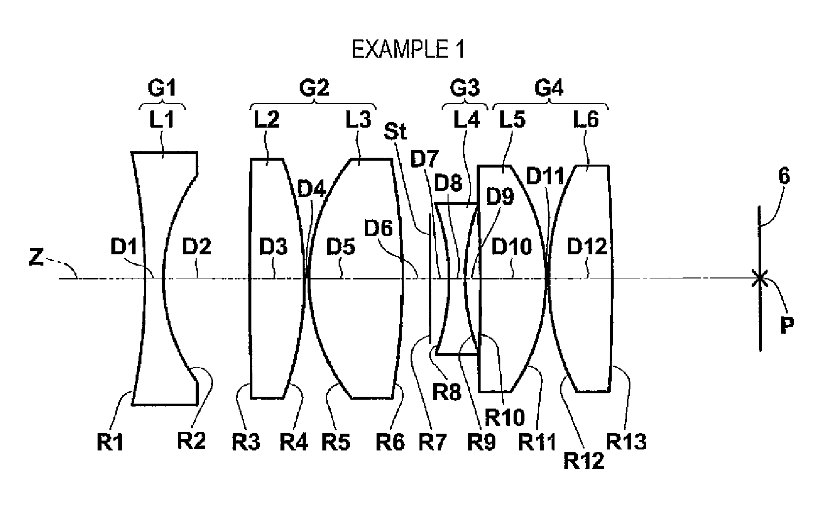
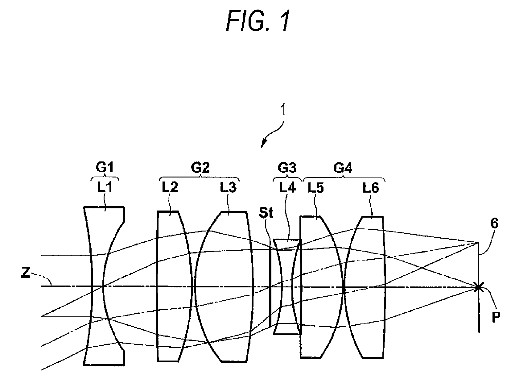
example 1
[0086]The specification values and the design specifications for an imaging lens according to an example 1 are shown in Table 1. In Table 1, surface numbers are provided in ascending order for i-th (i=1, 2, 3, . . . ) surfaces that are sequentially arranged in order from the surface of a component nearest to an object toward an image side. Ri indicates a radius of curvature for the i-th (i=1, 2, 3, . . . ) surface, and Di indicates on-axis surface spacing, along the optical axis Z, between the i-th (i=1, 2, 3, . . . ) surface and the (i+1)-th surface. Ndj indicates a refractive index at the d-line (wavelength 587.6 nm), of the j-th lens (j=1, 2, 3, . . . ), the surface number of which sequentially ascends from the lens nearest to the object as the first lens toward the image side. νdj indicates the Abbe number of the j-th lens at the d-line. A lens group correlated with the right-most column is denoted by a symbol. In Table 1, the unit “mm” is employed for a radius of curvature and ...
example 2
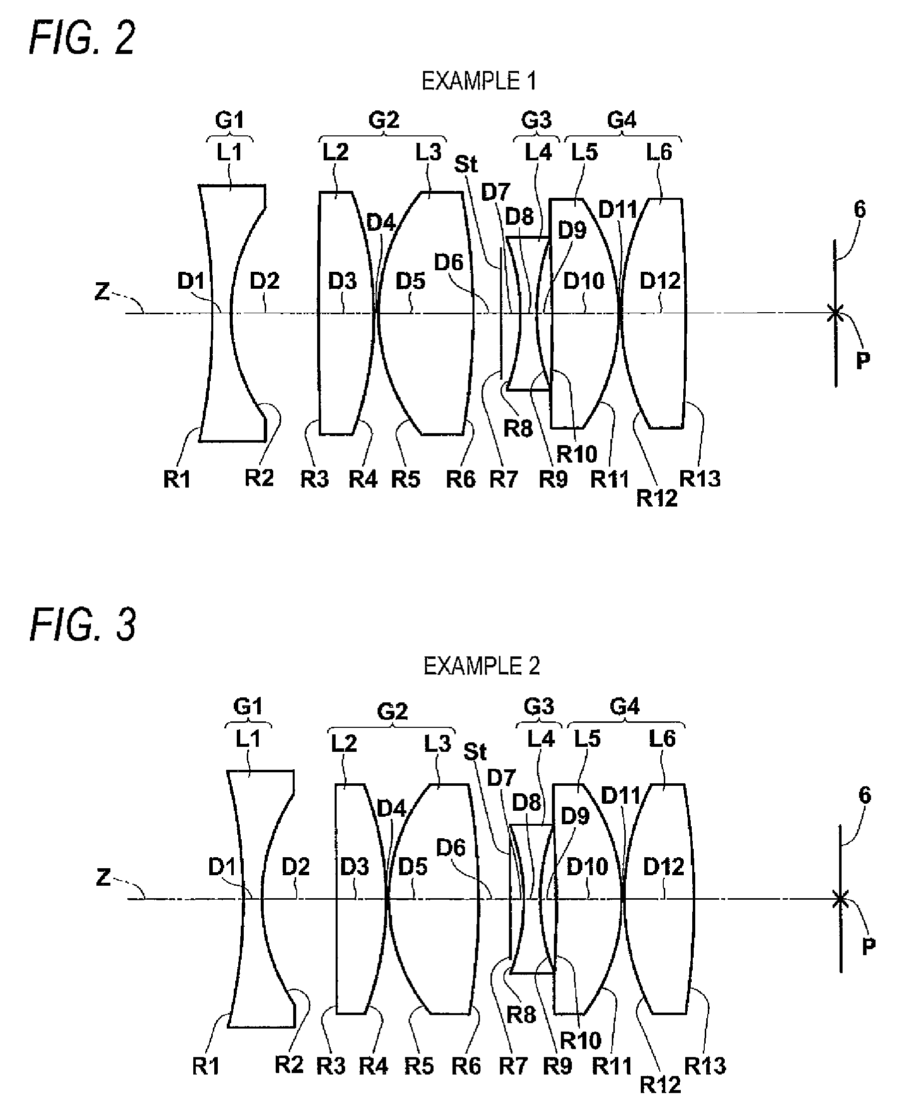
[0090]Specification values for an imaging lens of an example 2 are shown in Table 2, and a cross-sectional view of the lens structure thereof is shown in FIG. 3. In FIG. 3, symbols Ri and Di correspond to Ri and Di in Table 2.
[0091]
TABLE 2Example 2FNo. = 1.50, ω = 27.2°, IH = 2.675, f = 5.74, BF = 5.36, L = 16.73LensSurface NumberRiDiNdjνdjgroup1−19.76630.677761.772549.6G126.99322.761063∞1.879211.80135G24−11.54770.100956.61513.310551.75552.36−25.74871.15987 (aperture diaphragm)∞0.509658−7.67380.600141.9228618.9G397.67380.5882710−48.11892.43931.8348142.7G411−7.11340.1129.11612.607911.75552.313−27.3505
example 3
[0092]Specification values for an imaging lens of an example 3 are shown in Table 3, and the cross-sectional view of the lens structure thereof is shown in FIG. 4. In FIG. 4, symbols Ri and Di correspond to Ri and Di in Table 3.
[0093]
TABLE 3Example 3FNo. = 1.50, ω = 27.2°, IH = 2.675, f = 5.75, BF = 5.24, L = 17.70LensSurface NumberRiDiNdjνdjgroup1−17.10560.677811.8401642.7G127.13622.60612316.12613.604771.8328544.6G24−10.49060.1064157.07382.018531.7267955.1617.1562.059187 (aperture diaphragm)∞0.432058−8.96740.61.9228618.9G398.96740.4424410−361.472.505681.8485143.1G411−7.55210.1128.84412.550151.740745.3913−36.6385
PUM
 Abstract
Description
Claims
Application Information