
Method for uplink power control for distributed satellite networks to compensate for rain fade

a distributed satellite network and power control technology, applied in power management, channel coding adaptation, synchronisation signal speed/phase control, etc., can solve the problems of reducing the maximum allowed power of the amplifier, the output of most commercially available amplifiers tends to degrade in terms of spectral side-lobe and shoulder regrowth, and the existing solution does not meet the needs of bandwidth-on-demand satellite networks with diverse earth station configurations. , to achieve the effect of preserving the overall transmi

Inactive Publication Date: 2011-04-12
VIASAT INC
View PDF5 Cites 7 Cited by
  • Summary
  • Abstract
  • Description
  • Claims
  • Application Information

AI Technical Summary

Benefits of technology

This approach ensures improved link quality, reduces spectral regrowth, and optimizes power usage by dynamically adapting to weather-induced fades and amplifier degradations, effectively managing power in diverse network configurations and conserving satellite transponder resources.

Problems solved by technology

Networks have also evolved in complexity.
However, the output of most of the commercially available amplifiers tends to degrade in terms of spectral side-lobe and shoulder regrowth when operated close to or in saturation.
Very often, current methods require a wide power control dynamic range, and may drive the transmitter to operate in saturation, especially with changes over time and temperature.
However, existing solutions do not meet the needs of a Bandwidth-On-Demand satellite network with diverse earth station configurations.
Currently used methods do not ensure link quality between every dynamically varying transmit / receive pair on a burst-basis.
Such methods usually allocate a huge link margin that increases the transmit amplifier power requirement and hence drives up the cost.
Operating transmitters with a large built-in margin consumes excess satellite transponder power and decreases available transponder bandwidth capacity.

Method used


Image

  • Method for uplink power control for distributed satellite networks to compensate for rain fade
  • Method for uplink power control for distributed satellite networks to compensate for rain fade
  • Method for uplink power control for distributed satellite networks to compensate for rain fade

Examples


Embodiment Construction

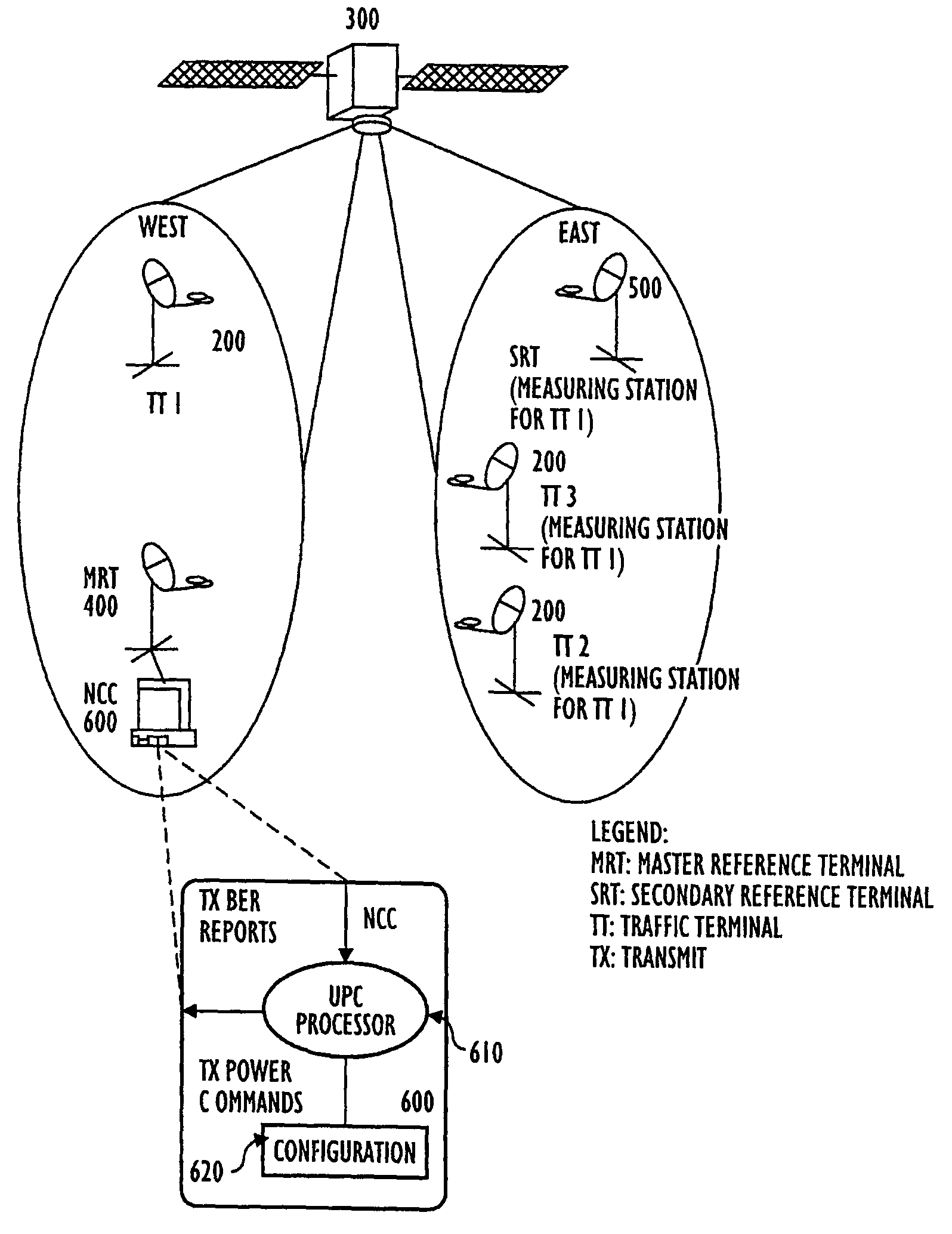
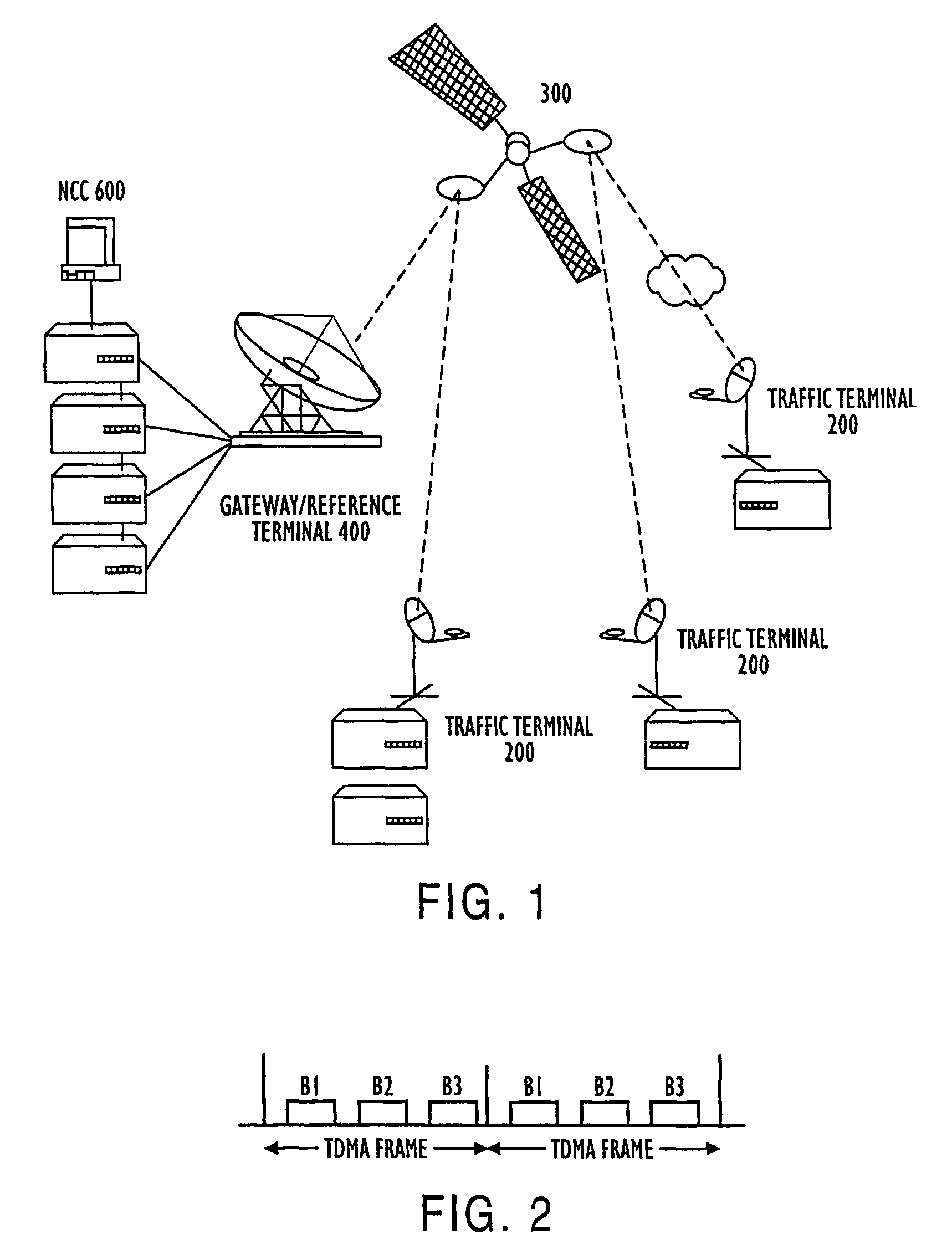
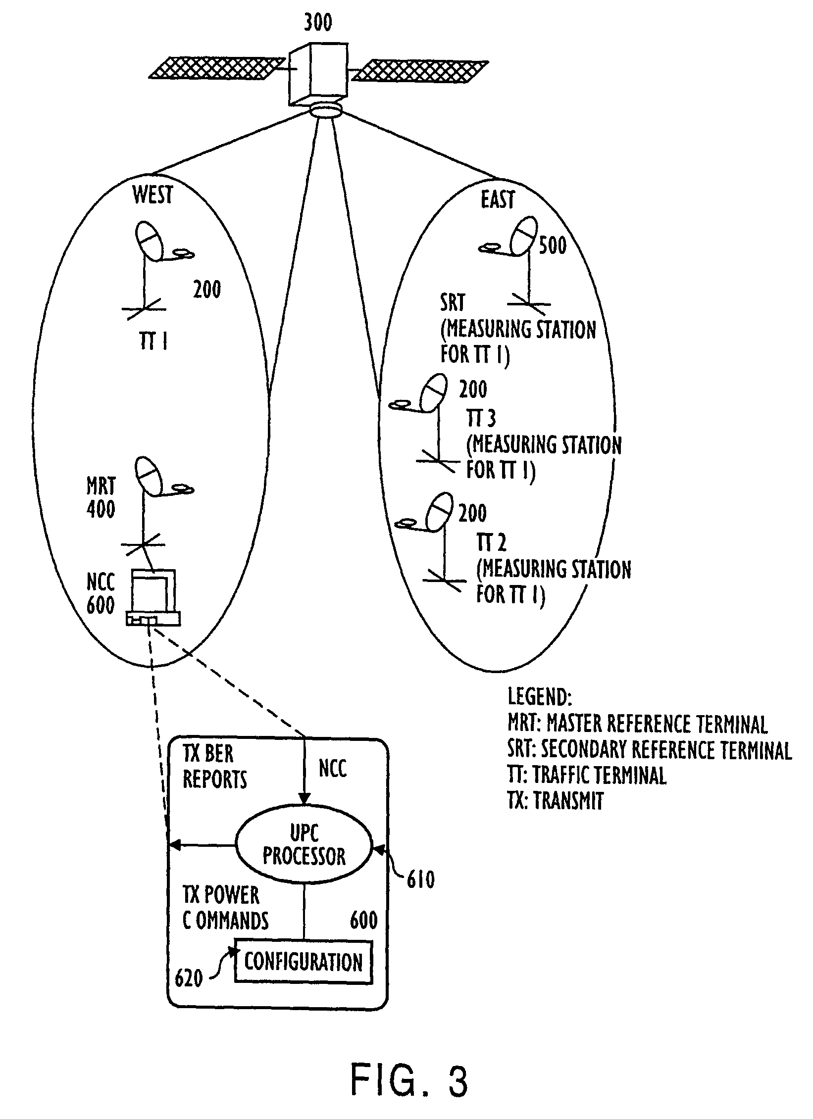
[0030]As previously mentioned, the methods for performing Uplink Power Control (UPC) in burst mode satellite / wireless networks rely on measurement of transmitter (uplink) link quality at multiple receiver (downlink) nodes in the distributed network. The link quality measurements are transferred to a central Network Control Center (NCC) computer, which computer implements a novel method for iteratively adjusting the transmit power on a per-burst basis to thereby achieve improved target link quality. This method features optimal response loop time constants to compensate for fast weather induced uplink fades as well as slow degradations in transmit amplifier power due to temperature variations and aging. Moreover, the NCC computer employs an additional method to dynamically detect the transmit power amplifier compression point and ensure sufficient input-back-off (IBO) under all conditions.

[0031]FIG. 1 illustrates a model of the network architecture employing the novel methods accordi...


PUM


Abstract

A method for dynamically determining the power compression point of an amplifier in a distributed network under the control of a computer, the network having a first terminal (600) including the amplifier operatively coupled to a plurality of second terminals (500) by a communication channel including the steps for generating bit error rate (BER) messages indicative of measured BER for a signal transmitted at N power levels, the BER messages including respective tags indicative of the N power levels for that BER, at the second terminals (500), and reducing the maximum allowed power of the amplifier when it is determined that the amplifier is approaching saturation responsive to the BER messages. Also described is a method for dynamic uplink power control for an amplifier in a distributed network.

Description

[0001]This is a continuation of application Ser. No. 09 / 529,773 filed Jun. 30, 2000 now U.S. Pat. No. 7,599,658, which is a National Stage Application filed under §371 of PCT Application No. PCT / US98 / 21632 filed Oct. 20, 1998, which claims benefit of Provisional Application Nos. 60 / 064,673, 60 / 062,496, and 60 / 062,497, all filed on Oct. 20, 1997. The entire disclosure of the prior application Ser. Nos. 09 / 529,773 is hereby incorporated by reference.[0002]This application is based on and claims priority from provisional patent applications, Ser. Nos. 60 / 064,673, 60 / 062,497 and 60 / 062,496, which are incorporated herein by reference for all purposes.BACKGROUND OF THE INVENTION[0003]The present invention relates generally to methods for uplink power control for satellite / wireless networks. More specifically, the present invention relates to methods for uplink power control for distributed satellite / wireless networks which compensate for rain fade and other equipment impairments. In addit...

Claims


Application Information

Patent Timeline
Patent Type & Authority Patents(United States)
IPC IPC(8): H04B7/185H04B7/005H04J3/00H04B7/15H04B7/208H04B7/212H04J3/06H04L7/033H04L7/10H04W52/28
CPCH04B7/18513H04B7/18543H04B7/208H04B7/2125H04W52/28H04L1/0083H04L1/0003H04L1/0009H04L1/0017H04L1/0025H04L1/0007
Inventor AGARWAL, ANIL K.HARIHARAN, MOORTHY N.
Owner VIASAT INC
Learn More