

Business process change analysis and test case adaptation based on change detection
a business process and change detection technology, applied in the field of business process change analysis and test case adaptation based on change detection, can solve the problems of high cost, time-consuming, and inability to meet the needs of business process change verification, and achieve the effect of reducing the cost of business process change verification
- Summary
- Abstract
- Description
- Claims
- Application Information
AI Technical Summary
Benefits of technology
Problems solved by technology
Method used
Image

Examples
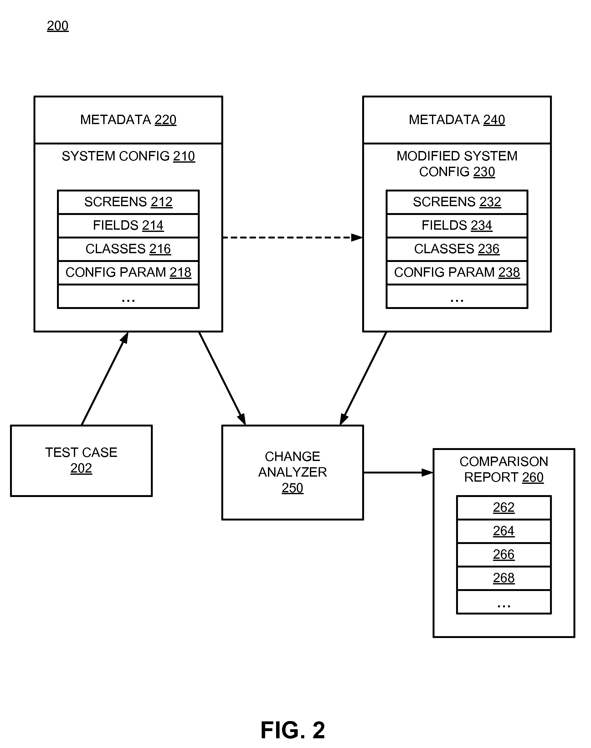
screens 212
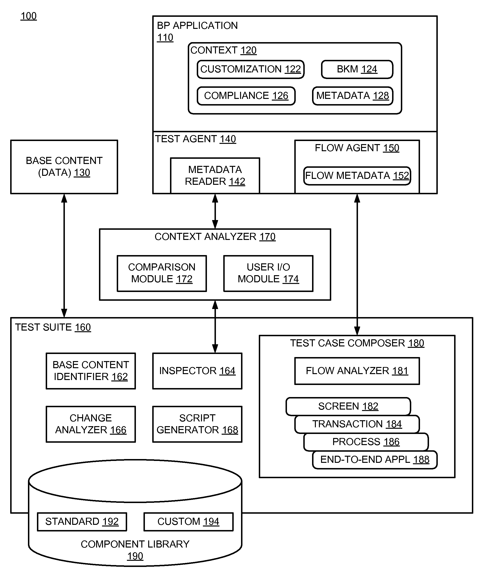
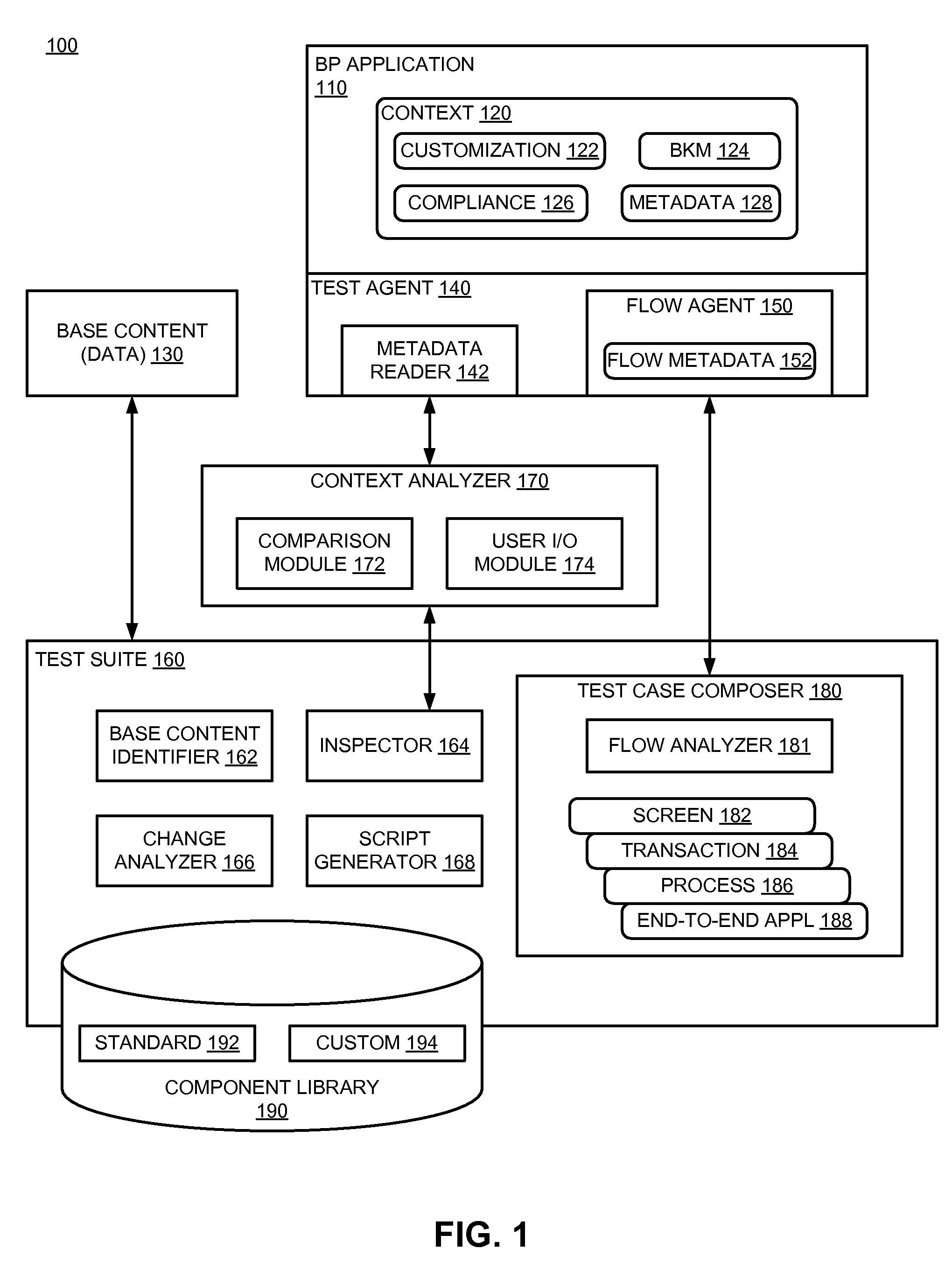
Screens 212 refer to UI layouts that present information to a user of the system in a particular format, with interactive fields. Certain fields may simply provide data, while others can receive input (e.g., mouse clicks, input parameters or values, selection of menus / items, etc.). One screen may transition to another screen upon selection of an item or inputting of a value. The difference in screens from one configuration to another may provide problematic for traditional test systems, which are generally unable to adapt to the change in screen content.
Fields 214 may refer, for example, to an interactive area of a screen. The name or designator of a field may be changed. The type of input required may also be modified. Classes 216 refer to object code from which specific instances of data are created. Configuration parameters 218 may include system configuration parameters, such as the system setup, physical resources, what components are installed, etc. Configuration parameters 21...
PUM
 Abstract
Description
Claims
Application Information