Method for the graphic planning of the control of a technical installation with integrated planning of operating devices including a planning system and a computer program product

Active Publication Date: 2011-08-30
SIEMENS AG
View PDF32 Cites 5 Cited by
  • Summary
  • Abstract
  • Description
  • Claims
  • Application Information

AI Technical Summary

Benefits of technology

[0015]Finally according to a further embodiment of the claimed method it is advantageous for the directory tree to have a third main branch, in which the connections to a data bus assigned to the graphic control objects are managed. Such a structure then provides an optimum overview and access to the most important levels, which have to be planned during automation of a technical process, namely the control level, the operating and monitoring level and the data transmission level, in particular via a field bus.
[0016]The claimed system for the graphic planning of a control for a technical installation has a planning window, graphic interaction means and planning means. The planning window thereby has a work area, which according to the invention is divided at least into one window for a symbol library containing the graphic objects available in the system for the planning of a technical installation, one window for a planning level for displaying and logically linking the graphic objects selected for the planning of a technical installation and one window for a directory tree of the graphic objects of planning selected in the window for the planning level. The graphic interaction means allow the selection of graphic objects in the window for the symbol library and the generation and logical linking of the selected graphic objects in the window for the planning level. The planning means then automatically adjust the directory of graphic objects in the window for the directory tree after generation of the selected graphic objects in the window for the planning level.
[0017]This claimed system allows the compact and per se closed planning of all graphic objects required for automation in a single planning tool. All types of graphic objects can hereby be processed in the same manner, depending on the content of

Problems solved by technology

This is complex a

Method used


Image

  • Method for the graphic planning of the control of a technical installation with integrated planning of operating devices including a planning system and a computer program product
  • Method for the graphic planning of the control of a technical installation with integrated planning of operating devices including a planning system and a computer program product
  • Method for the graphic planning of the control of a technical installation with integrated planning of operating devices including a planning system and a computer program product

Examples


Embodiment Construction

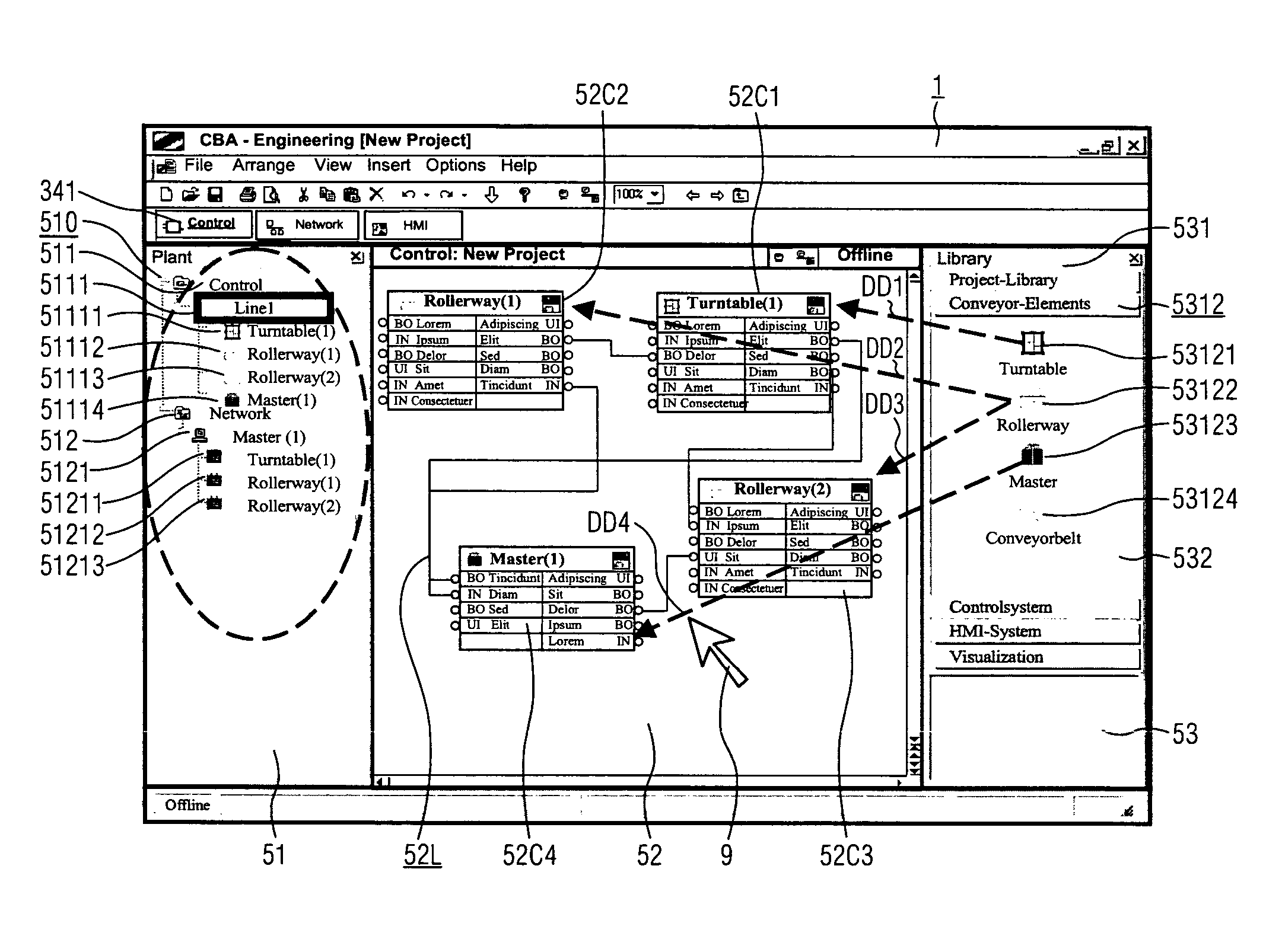
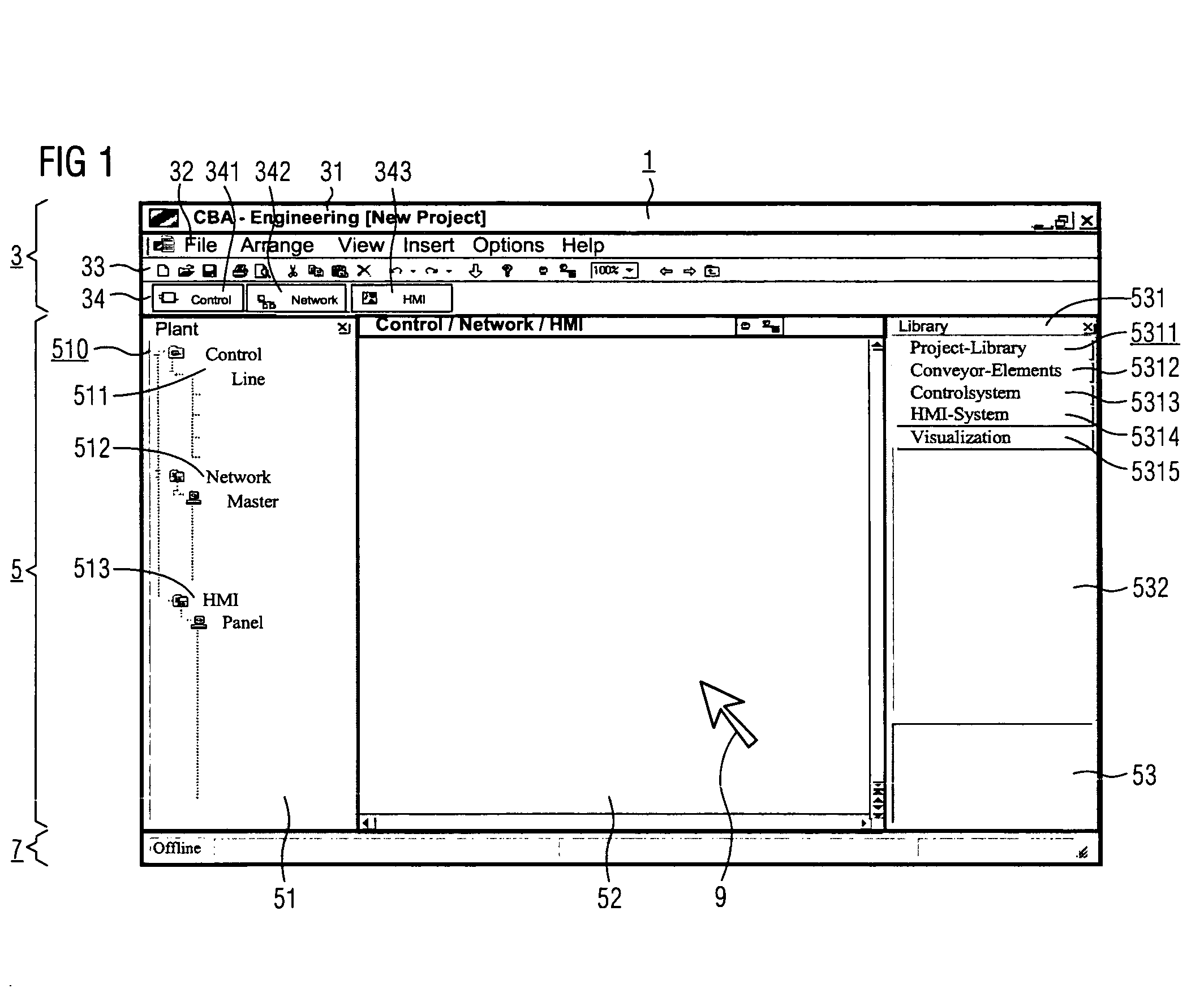
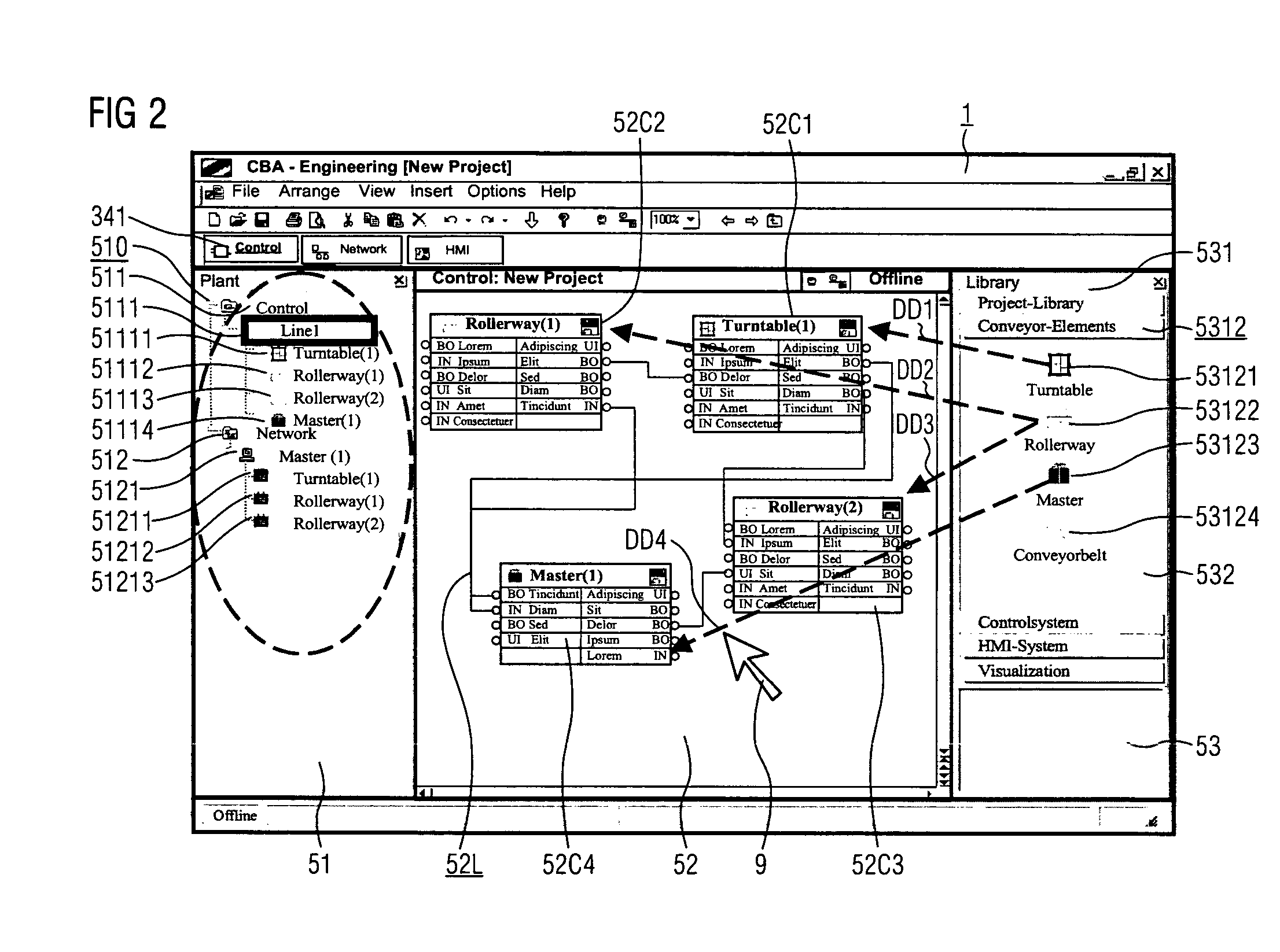
[0028]FIG. 1 shows an exemplary embodiment of a planning window 1 configured according to the claimed planning system. The planning window 1 is also the basis for the illustrations in the further FIGS. 2 to 7, which are used by way of an example to describe the individual steps of the claimed planning method.

[0029]The exemplary planning window 1 is divided horizontally by way of an example into three areas, i.e. an upper window area 1 for toolbars, a middle window area 5 for the work area, also referred to as the workbench, and a lower window area 7 for status information. The upper window area 1 contains four further toolbars in the example. The first toolbar 31 for the program and file display on the one hand contains a designation of the program name according to the conventions of windows-based programs. The claimed planning system in the example is thereby labeled with the designation “CBA—Engineering”, CBA being an abbreviation for component based automation. It is followed in...


PUM


Abstract

The inventive method interacts with a project planning window, which has a working area at least with one window for a project planning level for displaying and linking graphic objects and with a window for a symbol library containing the graphic objects available for a project planning. To this end, graphic control objects are provided, which represent technical objects of the installation and graphic control unit objects, which represent control units that can be used for a control. In a first step, the control objects of a project planning are activated in the window for the system library and transmitted into the project planning level. In a second step, the transmitted control objects are, in the window of the project planning level, subsequently linked in a logical manner according to a control task. In a third step, at least one control unit object is activated in the symbol library and transmitted into the project planning level. In a fourth step, the graphic control unit object is assigned to selected graphic control objects. The invention offers the advantage of enabling, in a closed project planning method, both the graphic control objects, which are required for controlling installation resources, as well as control unit objects, which are required for operating and monitoring the control, to be linked in a defined and logical manner.

Description

CROSS REFERENCE TO RELATED APPLICATION[0001]This application is the US National Stage of International Application No. PCT / EP2004 / 008349, filed Jul. 26, 2004 and claims the benefit thereof. The International Application claims the benefits of German Patent application No. 10339764.7 DE filed Aug. 27, 2003, both of the applications are incorporated by reference herein in their entirety.FIELD OF THE INVENTION[0002]The field of the invention is directed towards an inventive method that interacts with a project planning window, which has a working area at least with one window for a project planning level for displaying and linking graphic objects and with a window for a symbol library containing the graphic objects available for a project planning.BACKGROUND OF THE INVENTION[0003]It is known that the control of a technical installation by an automation system, e.g. a programmable logic controller, can be planned by means of graphic methods and mechanisms. SIEMENS for example uses Softw...

Claims


Application Information

Patent Timeline
IPC IPC(8): G06F9/44G05B19/042
CPCG06F8/38
Inventor MELZER, ROLANDPETER, MICHAELWIEDENBERG, PETER
Owner SIEMENS AG
Why Eureka
Try Eureka