
Industrial controller based on distributable technology objects

a technology object and industrial controller technology, applied in the field of industrial controllers, can solve the problem of limited expansion, and achieve the effect of expanding the functionality of industrial controllers

Inactive Publication Date: 2009-05-14
SIEMENS AG
View PDF42 Cites 4 Cited by
  • Summary
  • Abstract
  • Description
  • Claims
  • Application Information

AI Technical Summary

Benefits of technology

[0011]A technology object preferably represents a component of the real world. In the context of industrial controllers, these may be, for example, components of machine tools or production machines. Technology objects provide a defined, closed technological functionality. They may be interleaved with one another to implement complicated technological tasks. Because the technological functionality of the controller is formed by technology objects, which are preferably real components, the technology capability (i.e., the capability of the controller) is immediately transparent to a user of the controller. A technology object may also very easily be reused by a user as a technological software unit in different applications and controllers. A user can abstract objects from their implementation when using technology objects. Technology objects that can be used directly by the user in his user programs are obtained by instantiation from technology object types. Any desired number of instances of technology objects can be obtained from a technology object type once it has been defined. Because instantiation can take place in the engineering system or in the run time system, it is convenient and easy for the user to use the technology objects in his applications. The functional capability of a controller can thus be expanded very easily. This expandability is limited only by hardware restrictions (e.g., CPU, power or memory restrictions).
[0033]Another advantage of the claimed invention is that the functionality of industrial controllers can be expanded in a dedicated manner by the so-called “plug-and-play” system. Technological scaling of the controller can be achieved in this way.

Problems solved by technology

This expandability is limited only by hardware restrictions (e.g., CPU, power or memory restrictions).

Method used


Image

  • Industrial controller based on distributable technology objects
  • Industrial controller based on distributable technology objects
  • Industrial controller based on distributable technology objects

Examples


Embodiment Construction

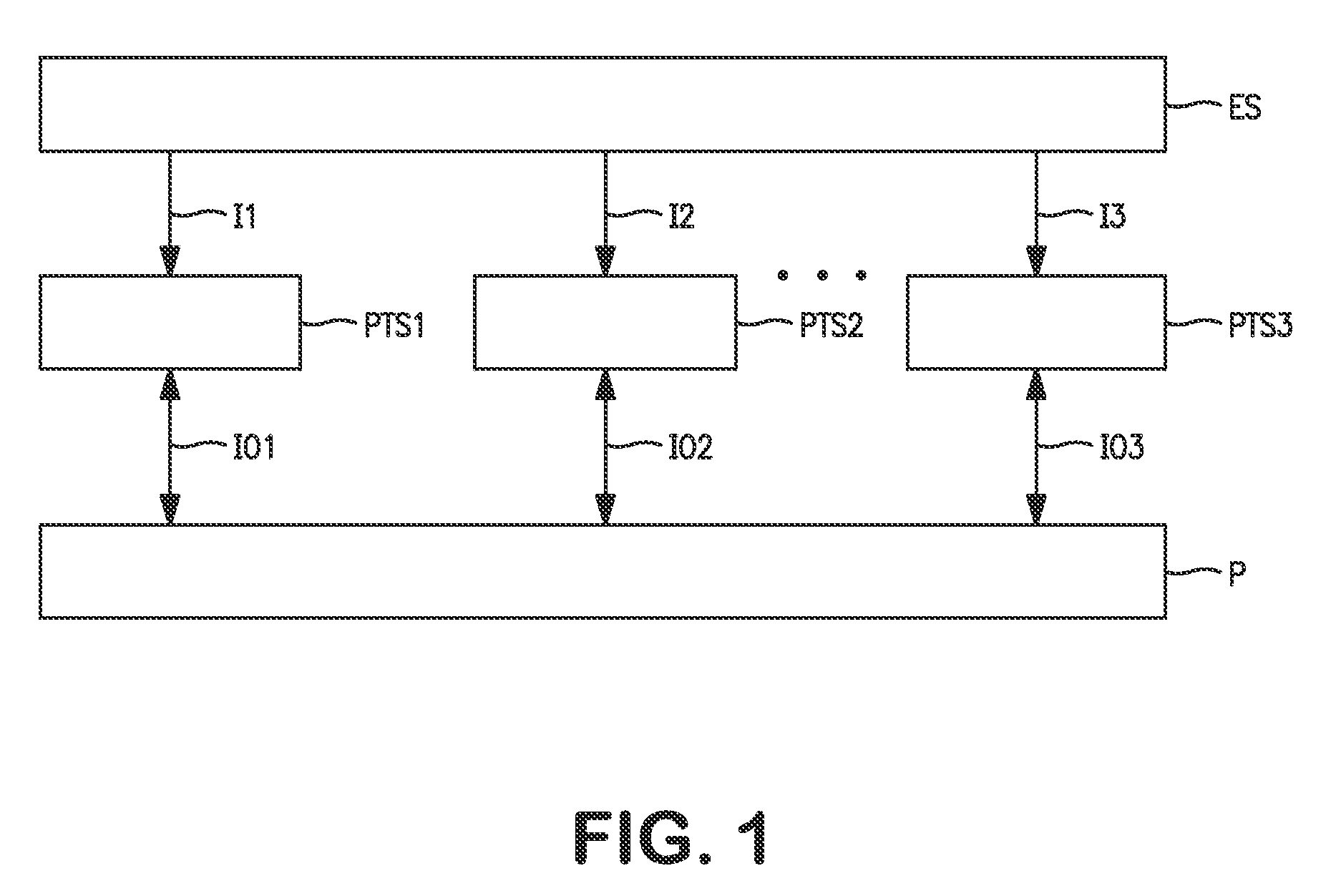
[0045]In the form of a block diagram, FIG. 1 shows that a technical process P may be controlled over at least one run time system RTS1-RTS3 of an industrial controller. The connection between the run time systems RTS1-RTS3 of the controller and the technical process P is bidirectional over inputs / outputs IO1-IO3. The controller is programmed and the definition of the performance of run time systems RTS1-RTS3 defined, using engineering system ES. Engineering system ES contains tools for configuring, designing and programming for machines and the controllers of technical processes. Programs generated in engineering system ES are transmitted over information paths I1-I3 to run time systems RTS1-RTS3 of the controllers. The three dots between RTS2 and RTS3 indicate that additional controllers and run time systems may be present. With regard to its hardware, an engineering system ES may comprise a computer system with a graphic display screen (e.g., a display), input means (e.g., keyboar...


PUM


Abstract

A method and system for controlling an industrial controller based on technology objects are disclosed. Technology object types may be loaded and instantiated into the run time system of a controller, thereby increasing the functionality and providing technological scaling of the controller. Technology object types may be loaded in the form of technology packages and a user may use the functionality of the invention directly in a user program.

Description

PRIORITY[0001]This application claims priority and is a continuation of co-pending U.S. patent application Ser. No. 11 / 093,155 entitled “INDUSTRIAL CONTROLLER BASED ON DISTRIBUTABLE TECHNOLOGY OBJECTS,” filed on Mar. 28, 2005, which claims priority to U.S. patent application Ser. No. 09 / 895,904, filed Jun. 29, 2001, now U.S. Pat. No. 6,882,890, entitled “INDUSTRIAL CONTROLLER BASED ON DISTRIBUTABLE TECHNOLOGY OBJECTS,” both of which are hereby incorporated by reference in their entirety.FIELD OF THE INVENTION[0002]This invention relates to an industrial controller for technical processes, in particular for production machines.[0003]Specifically, this invention also relates to a method of creating an industrial controller, in particular for a certain area of application, e.g., for use in packaging machines.BACKGROUND[0004]An industrial controller may be a separate device or it may be integrated into a computer, a PC, a stand-alone unit or a drive.[0005]Prior industrial controllers kn...

Claims


Application Information

Patent Timeline
Patent Type & Authority Applications(United States)
IPC IPC(8): G05B11/01G06F9/44G05B19/042G05B19/418
CPCG05B19/41865G05B19/0426Y02P90/02
Inventor HORN, WOLFGANGBIRZER, JOHANNESHEBER, TINOKRAM, RAIMUNDKIESEL, MARTIN
Owner SIEMENS AG
Learn More