
Tension-controlled web processing machine and method

a web processing machine and control technology, applied in the field of semi-rotary web processing machines, can solve the problems that the semi-rotary process modules cannot be used in series with other modules, and the registry of the web at each module can be a complex procedur

Inactive Publication Date: 2011-04-19
DURST PHOTOTECHN
View PDF16 Cites 2 Cited by
  • Summary
  • Abstract
  • Description
  • Claims
  • Application Information

AI Technical Summary

Benefits of technology

[0008]It is also an aim of the present invention to provide an improved method for processing a web.
[0009]It is a further aim of the present invention to provide an improved system for conveying a web between a tool cylinder and a corresponding anvil cylinder.
[0010]Therefore, in accordance with the present invention, there is provided a web processing assembly for a web processing module, the assembly comprising first, second and third fixed spaced apart pairs of nip rollers moving the web at a first, second and third speeds, the first and third speeds being constant and similar, the second speed being variable with a mean speed similar to the first and third speeds, and a first idler roller engaging the web between the first and second pair of rollers and a second idler roller engaging the web between the second and third pair of rollers, each of the first and second idler rollers maintaining the web in constant tension by moving along a restrained path perpendicular to an axis of the respective one of the first and second idler rollers to compensate for a difference between the variable second speed and the respective one of the constant first and third speeds.

Problems solved by technology

In most cases however, the modules performing the semi-rotary process cannot be used in series with other modules, since the web exiting the module usually travels at an intermittent speed, and as such is not compatible with a rotary process.
However, in such series the modules are usually dependent on one another for maintaining the web in tension, and as such a registry error at one module is reflected in all the downstream modules.
As such, registry of the web at each module can be a complex procedure, usually done through modifying the speed or position of the multiple tool cylinders.

Method used


Image

  • Tension-controlled web processing machine and method
  • Tension-controlled web processing machine and method
  • Tension-controlled web processing machine and method

Examples


Embodiment Construction

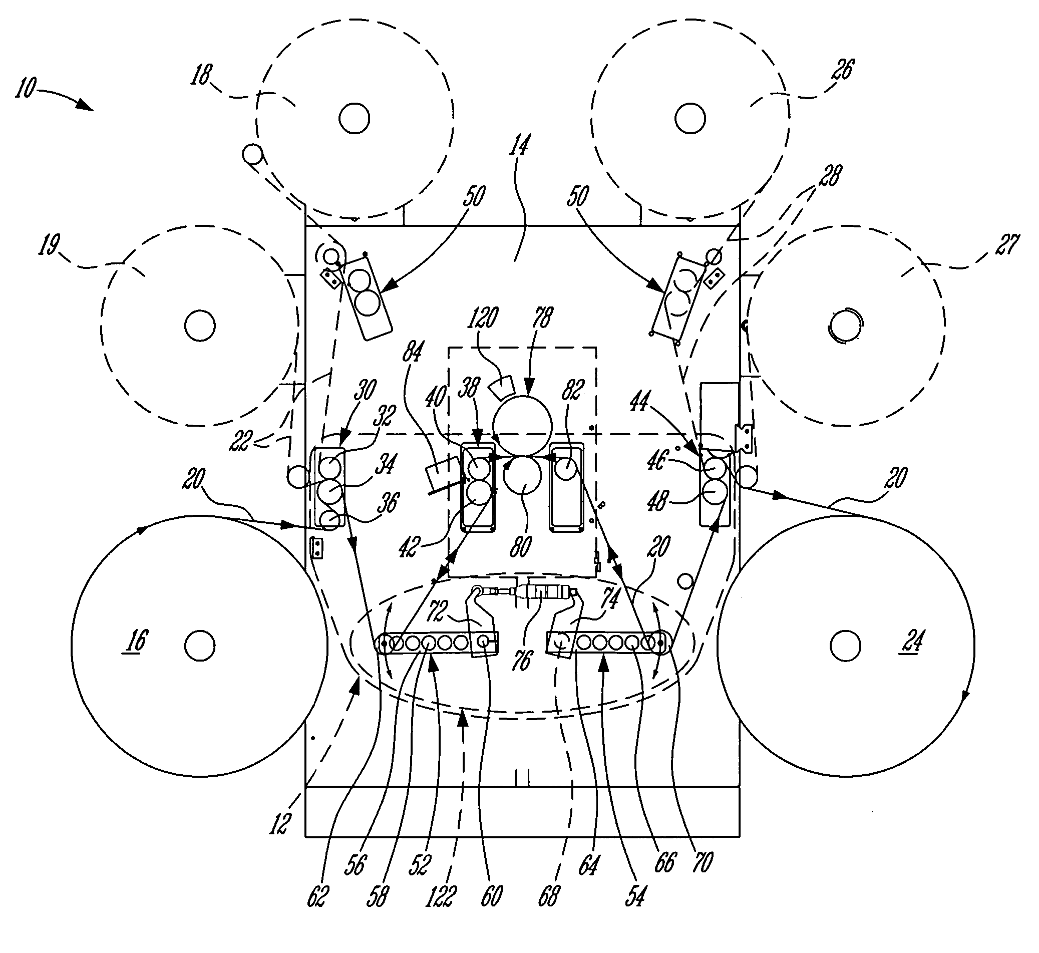
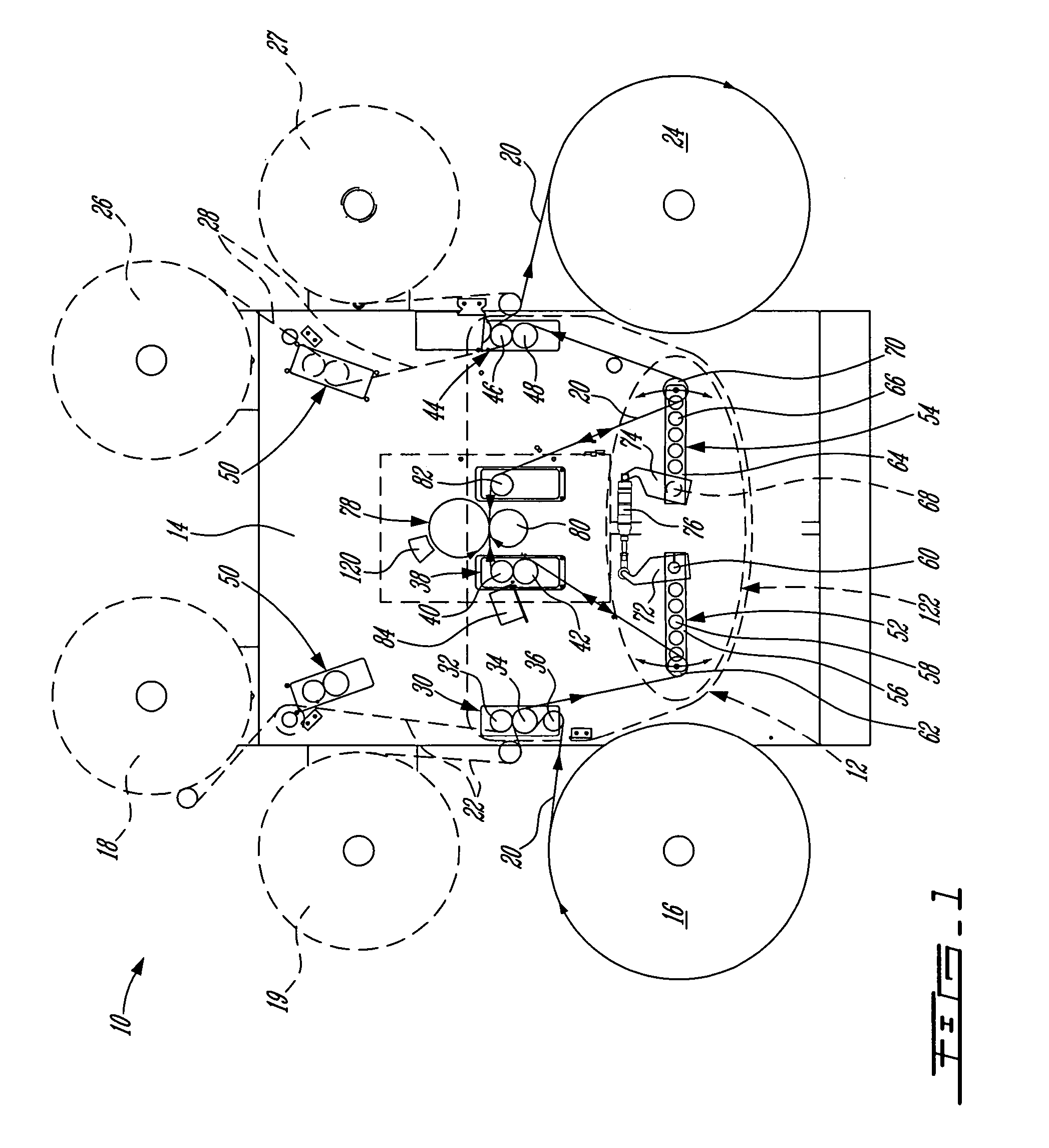
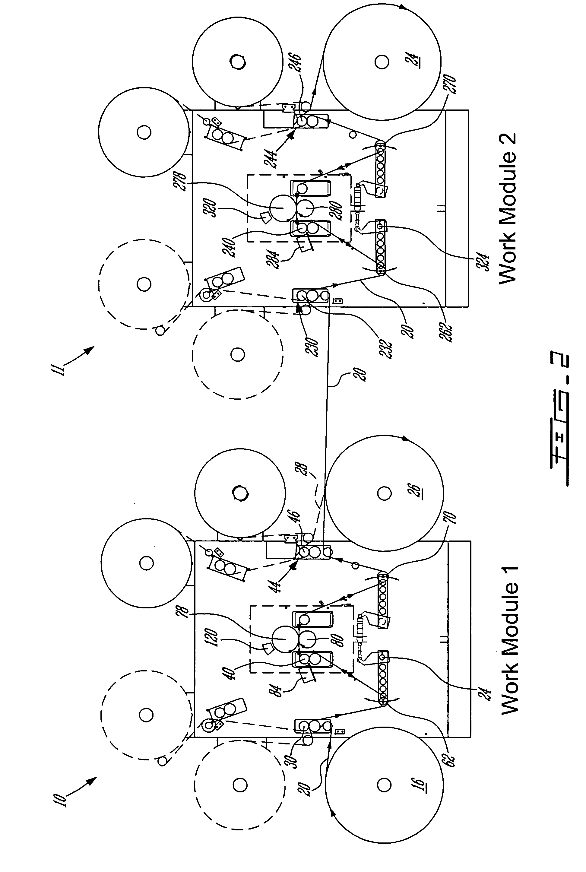
[0022]Referring now to FIG. 1, a web processing module 10 according to the present invention is schematically shown. The web processing module 10 includes a body 14 supporting a web processing assembly 12, an unwind roll 16 preferably including lateral registering means (not shown), a tool cylinder 78 driven by an anvil cylinder 80, and rewind roll 24. The web processing assembly 12 allows a web 20 to be pulled from the unwind roll 16 at a constant speed, processed by the rotating tool cylinder 78 at a cycling speed or a constant speed, as required, and rewound on the rewind roll 24 at a constant speed. The web 20 can be, for example, paper, plastic film, label stock, etc. The unwind and / or rewind rolls 16,24 can be omitted if the web processing module 10 receives the web 20 from and / or feeds the web 20 to another web processing module.

[0023]The tool cylinder 78 can be, for example, a printing cylinder, a stamping cylinder, a die cutting cylinder, an embossing cylinder, a coating cy...


PUM

PropertyMeasurementUnit
speedsaaaaaaaaaa
speedaaaaaaaaaa
tensionaaaaaaaaaa

Abstract

A web processing assembly including first, second and third fixed spaced apart pairs of nip rollers moving the web respectively at a first, second and third speeds, the first and third speeds being constant and similar, the second speed being variable with a mean speed similar to the first and third speeds, a first idler roller engaging the web between the first and second pair of rollers and a second idler roller engaging the web between the second and third pair of rollers, each idler roller maintaining the web in constant tension by moving along a restrained path perpendicular to its axis to compensate for a difference between the variable second speed and the respective one of the constant first and third speeds. A method for processing a web and system for conveying a web are also disclosed.

Description

BACKGROUND OF THE INVENTION[0001]1. Field of the Invention[0002]The present invention relates to web processing machines, particularly to semi-rotary web processing machines.[0003]2. Background Art[0004]Web processing machines using a rotating tool cylinder processing successive sections of a continuous web of material include for example machine performing die cutting, laminating, stamping, printing, and coating. The successive sections are usually identical (i.e. repeats), and can be for example shapes to be cut, printed images, etc. The rotating tool is usually required to have the same tangential speed as the linear speed of the web when the tool is used to process each section of the web.[0005]When the speed of the tool cylinder rotation and of the web are constant, the length of one section of web to be processed is usually equal to the circumference of the tool cylinder. As such, changing the length of the sections usually implies changing the tool cylinder. To reduce costs, ...

Claims


Application Information

Patent Timeline
Patent Type & Authority Patents(United States)
IPC IPC(8): B65H20/02B65H20/24B65H23/185B65H23/192B65H23/198
CPCB26D7/14B65H23/1882B26F1/384Y10T83/768Y10T83/0515
Inventor DUPUIS, LOUISHOGE, ROSSKOEHLER, JAMES
Owner DURST PHOTOTECHN
Learn More