Chassis arrangement with stabilizing system for controlling a driving stability of a motor vehicle

a technology of stabilizing system and chassis, which is applied in the direction of interconnection system, resilient suspension, vibration damper, etc., can solve the problems of hydraulic actuators and electric motors, energy-intensive control performance implementation, and not entirely suitable to influence the vibration of the vehicle body, so as to improve the ability to dynamically determin

Inactive Publication Date: 2011-04-19
BENTELER AUTOMOBILTECHNIK GMBH
View PDF13 Cites 6 Cited by
  • Summary
  • Abstract
  • Description
  • Claims
  • Application Information

AI Technical Summary

Benefits of technology

[0010]The present invention resolves prior art problems by arranging a bearing between the confronting ends of the stabilizer portions so as to mutually support the stabilizer portions, and by constructing the brake unit as a disk brake. As a result, the stiffness against rotation of the stabilizer can be adjusted without the need for one or more actuators. Still, the rolling rate and thus the vehicle body vibration can be influenced cycle-dependent. Compared to conventional proposals, a chassis arrangement according to the invention is more cost-efficient to manufacture, weighs less, and consumes less energy for operation.
[0028]According to another feature of the present invention, the controller may be operatively connected to a sensor assembly. The senor assembly enables establishment of a closed loop that permits an effective control of the chassis arrangement. The sensor assembly may include at least one acceleration sensor which may be structured to ascertain a transversal acceleration and thus to determine a rolling tendency. The sensor assembly may also include a plurality of acceleration sensors for ascertaining accelerations in different effective directions. As a result, further acceleration vectors, in particular in travel direction, can be determined in addition to the transversal acceleration. The sensor assembly may also include at least one speed sensor by which a speed-dependent control of the chassis arrangement can be realized, and a sensor for ascertaining the condition of a road surface, in particular with respect to a road surface temperature. Suitably, a sensor for detecting a wheel carrier compression may be arranged at one wheel carrier, preferably each wheel carrier. Such a sensor is better able to dynamically determine spring compression. The sensor assembly may also include a sensor for ascertaining meteorological data. Examples of meteorological data include outside temperature, presence of rain and intensity thereof.

Problems solved by technology

However, for a number of reasons, the various proposals are endowed with drawbacks and shortcomings relating for example to their very complex configuration or to the effect that is hoped to be obtained but may not always be realized.
In addition, they are very energy-intensive to implement the control performance.
Also, hydraulic actuators and electric motors operate very sluggishly and thus are not entirely suitable to influence vehicle body vibration in dependence on the vibration cycle.

Method used


Image

  • Chassis arrangement with stabilizing system for controlling a driving stability of a motor vehicle
  • Chassis arrangement with stabilizing system for controlling a driving stability of a motor vehicle
  • Chassis arrangement with stabilizing system for controlling a driving stability of a motor vehicle

Examples


first embodiment

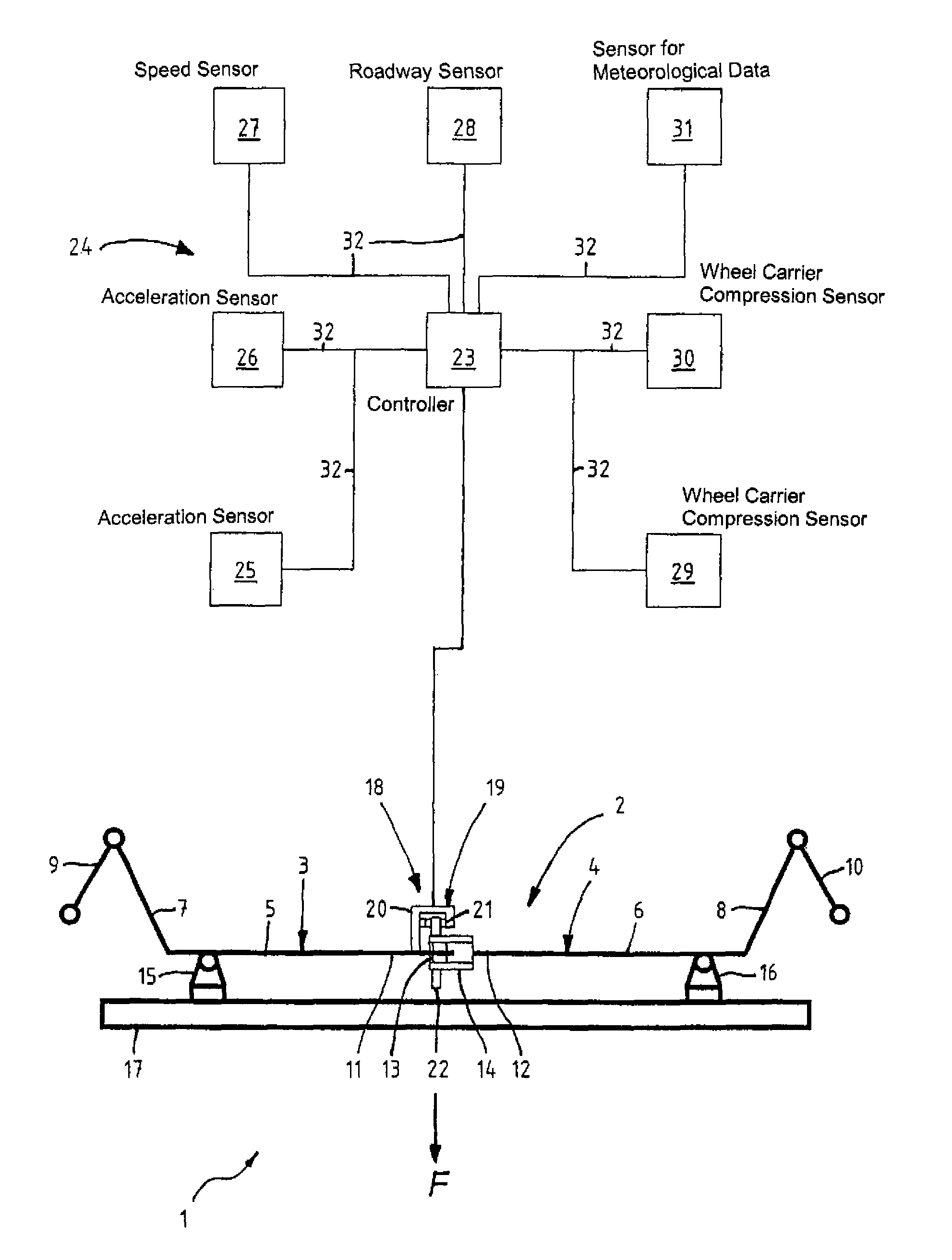
[0038]Turning now to the drawing, and in particular to FIG. 1, there is shown a chassis arrangement according to the present invention, generally designated by reference numeral 1, for a motor vehicle, not shown in greater detail. The chassis arrangement 1 includes a stabilizer 2 which has a first stabilizer portion 3 and a second stabilizer portion 4 which are separated from one another in midsection of the stabilizer 2. Reference sign F designates a travel direction of the motor vehicle. The stabilizer portion 3 has an inner part 5 which is made torsionally yielding and is continued externally by a stabilizer arm 7 for attachment of the stabilizer 1 to a wheel carrier unit 9. Likewise, the stabilizer portion 4 has an inner part 6 which is made torsionally yielding and continued externally by a stabilizer arm 8 for attachment of the stabilizer 1 to a wheel carrier unit 10. A bearing unit 13 is arranged between neighboring ends 11, 12 of the stabilizer portions 3, 4 for mutual suppo...

second embodiment

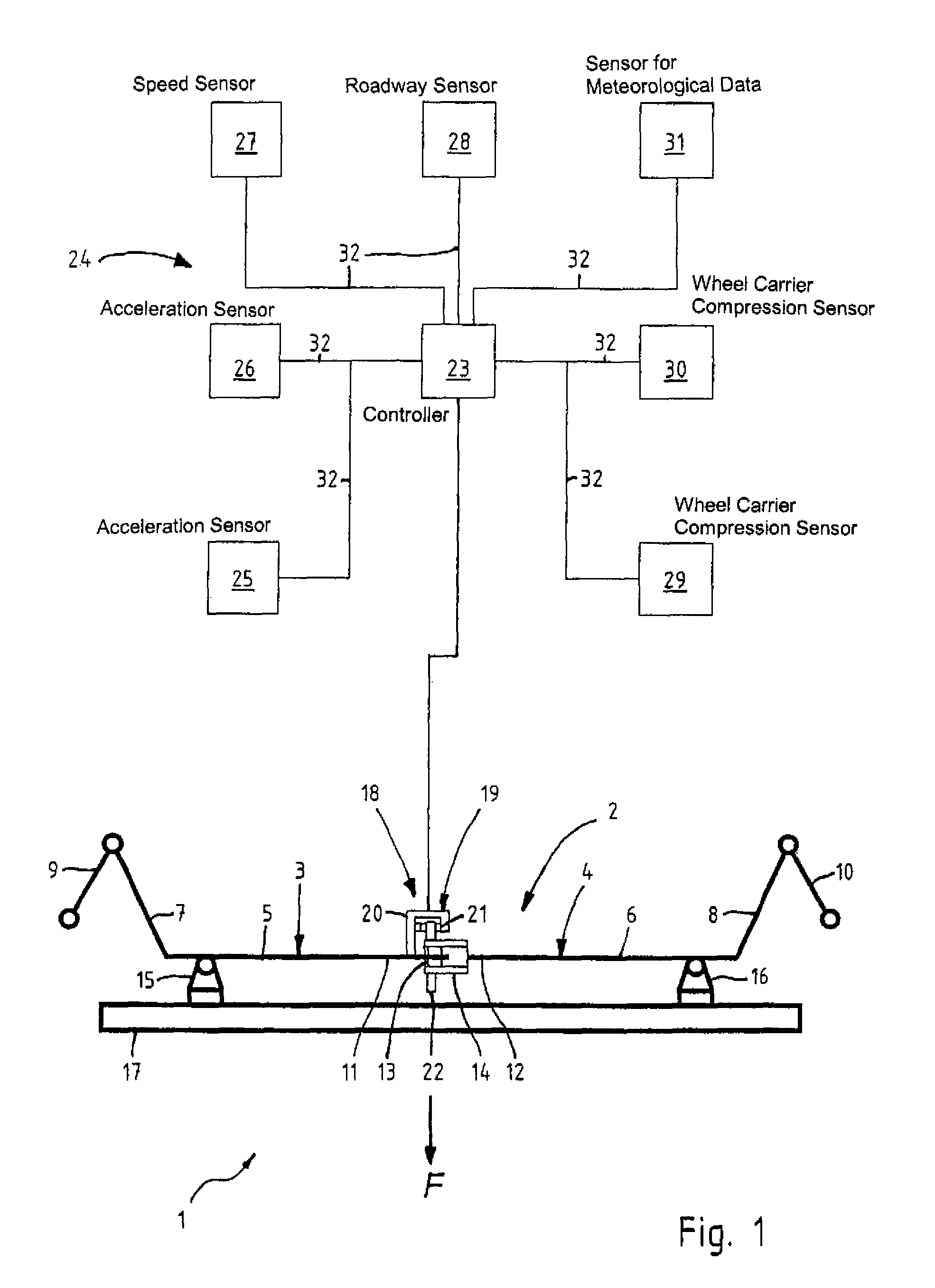
[0041]FIG. 2 shows a schematic top plan view of a chassis arrangement according to the present invention, generally designated by reference numeral 50. The chassis arrangement 50 includes a stabilizer 51 having a single-piece center part 52 and stabilizer arms 53, 54, connected to respective ends of the center part 52. The center part 52 is made torsionally yielding and supported by two stabilizing supports 55, 66 with rolling-contact bearings 57, 58 on a vehicle body 59.

[0042]Detachably secured to the center part 52 are two brake units 60, 61 by which the twistability of the center part 52 can be modified. The brake units 60, 61 are supported by the vehicle body 59 and constructed as disk brakes 62, 63, with disk brake 62 having a brake disk 77 and disk brake 63 having a brake disk 78. Brake unit 60 is arranged between the stabilizer support 55 and the adjacent stabilizer arm 53, whereas brake unit 61 is arranged between the stabilizer support 56 and the adjacent stabilizer arm 54....

third embodiment

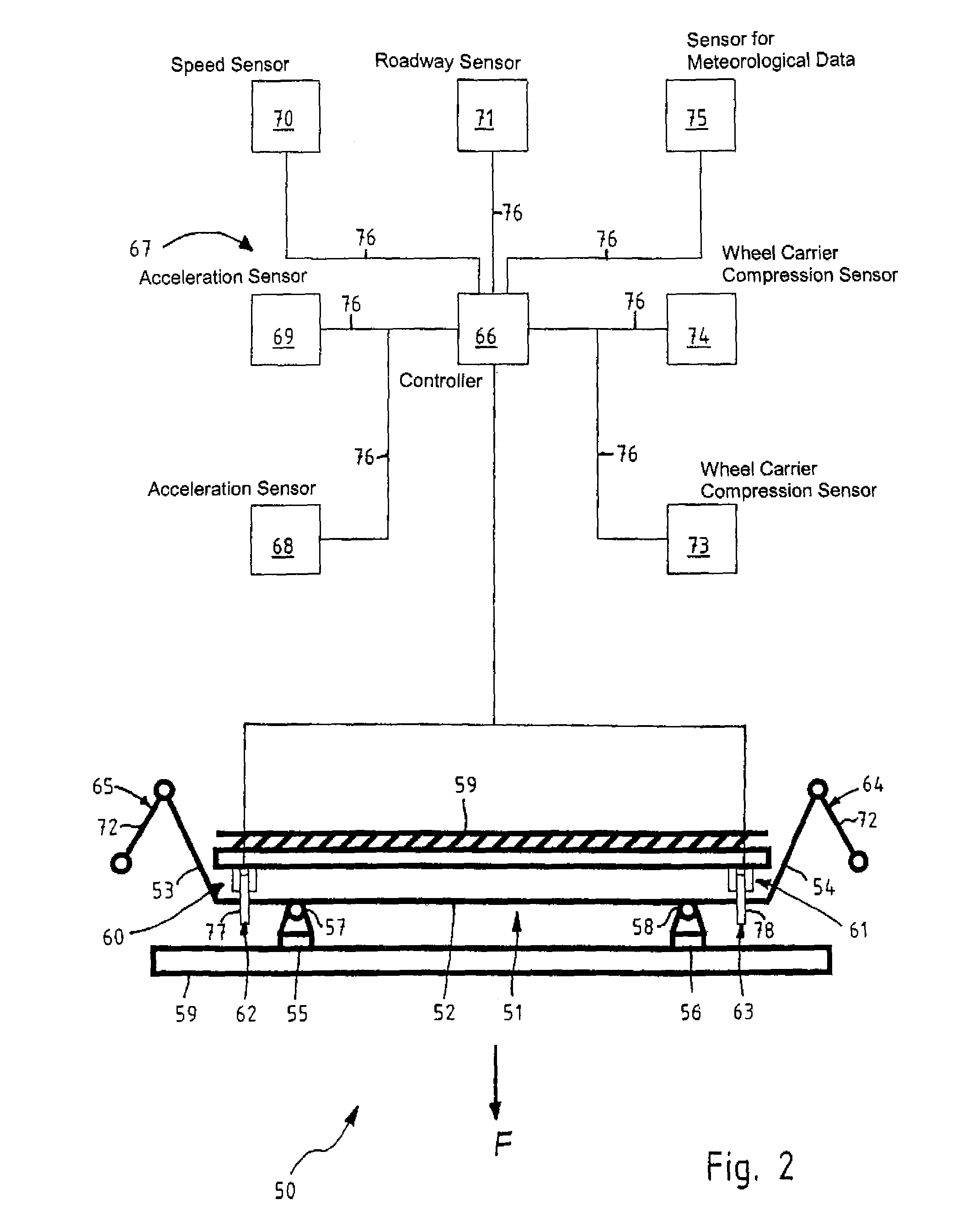
[0044]FIG. 3 shows a schematic top plan view of a chassis arrangement according to the present invention, generally designated by reference numeral 101. The chassis arrangement 101 includes a stabilizer 102 having a first stabilizer portion 103 and a second stabilizer portion 104 which are separated from one another in midsection of the stabilizer 102. The stabilizer portions 103, 104 are coupled to one another by a device 105 for influencing the relative rotation between the stabilizer portions 103, 104. The stabilizer portion 103 has an inner part 106 which is made torsionally yielding whereas the stabilizer portion 104 has an inner part 107 which is also made torsionally yielding. Stabilizer arms 108, 109 connect to respective ends of the inner parts 106, 107 for attachment of the stabilizer 102 to wheel carrier units 110, 111. The stabilizer portions 103, 104 are supported on a vehicle body 116 by respective stabilizer supports 112, 113 with rolling-contact bearings 114, 115.

[00...


PUM


Abstract

A chassis arrangement includes a stabilizer having a single-piece center part with opposite ends, a first stabilizer arm connected to one of the opposite ends of the center part, and a second stabilizer arm connected to the other one of the opposite ends of the center part. A stabilizer support assembly having two support units supports the center part in relation to a vehicle body. Operatively connected to the center part are at least two brake units for influencing a twistability of the center part, with one of the brake units being arranged between one of the support units and an adjacent one of the first and second stabilizer arms, and the other one of the brake units being arranged between the other one of the support units and an adjacent one of the first and second stabilizer arms.

Description

CROSS-REFERENCES TO RELATED APPLICATIONS[0001]This application claims the priority of German Patent Applications, Serial No. 10 2006 008 995.2, filed Feb. 23, 2006, and 10 2006 012 110.4, filed Mar. 14, 2006, pursuant to 35 U.S.C. 119(a)-(d), the contents of which are incorporated herein by reference in its entirety as if fully set forth herein.BACKGROUND OF THE INVENTION[0002]The present invention relates, in general, to a chassis arrangement with a stabilizing system for controlling a stability of a motor vehicle during travel.[0003]Nothing in the following discussion of the state of the art is to be construed as an admission of prior art.[0004]Motor vehicles have stabilizers for compensating a rolling tendency of the vehicle as a consequence of a transversal acceleration when negotiating a curve. A stabilizer is operatively connected to a vehicle axle to introduce a support torque in opposition to the rolling torque in wheel carrier units. Normally both axles are equipped with a ...

Claims


Application Information

Patent Timeline
Patent Type & Authority Patents(United States)
IPC IPC(8): B60R21/055
CPCB60G17/016B60G21/0555B60G21/0556B60G2204/11B60G2400/104B60G2400/106B60G2600/20B60G2400/821B60G2400/822B60G2400/8422B60G2400/8424B60G2400/843B60G2400/204
Inventor ZUBER, ARMIN
Owner BENTELER AUTOMOBILTECHNIK GMBH
Why Eureka
Try Eureka