
Dial control with LED light ring

a technology of led light and dial control, which is applied in the direction of mechanical control devices, domestic stoves or ranges, instruments, etc., can solve the problems of restricting the ability of designers

Active Publication Date: 2011-04-19
ILLINOIS TOOL WORKS INC
View PDF9 Cites 24 Cited by
  • Summary
  • Abstract
  • Description
  • Claims
  • Application Information

AI Technical Summary

Benefits of technology

The present invention provides an illuminated dial control for an appliance or the like that provides even illumination of sectors around the dial operator. The control includes arcuate chambers positioned about the dial operator and light diffusers on the front surfaces of the chambers. The light emitting diodes (LEDs) are positioned at the back surface of the reflective chambers and a reflective chamber cap is positioned to provide uniform colored illumination. The control also includes a gas valve operated by the dial operator and a printed circuit board supporting the light diffusers and LEDs. The invention provides a simplified manufacturing process and a more visually appealing control.

Problems solved by technology

Unfortunately the colors and shapes of such lamps are limited and thereby constrain the ability of the designer of an appliance to produce attractive and functional control consoles.

Method used


Image

  • Dial control with LED light ring
  • Dial control with LED light ring
  • Dial control with LED light ring

Examples


Embodiment Construction

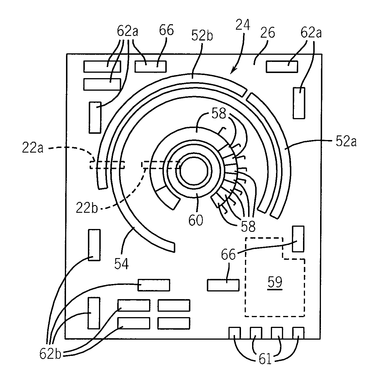
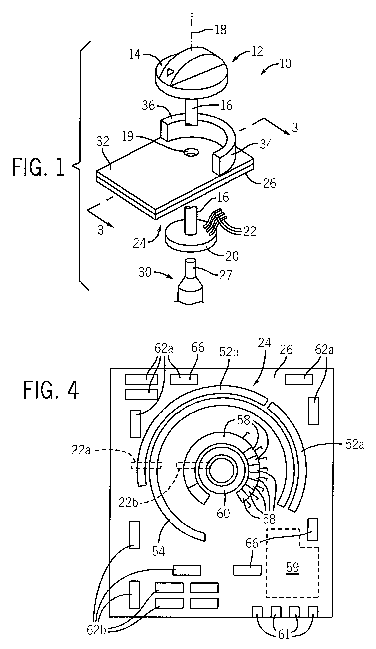
[0043]Referring now to FIG. 1, the dial control 10 of the present invention includes an operator 12, for example, a knob 14 having a shaft 16 extending along an axis 18. The shaft 16 may pass through a hole 19 in a molded lamp housing 32 and a printed circuit board 26 to attach to a wiper plate 20 holding a first set of electrical wipers 22. The wiper plate 20 rotates with the shaft 16 and electrical wipers 22 may connect with a set of electrical contacts 24 on the bottom of a printed circuit board 26 in the manner of a rotary switch. The lower end of shaft 16 may also connect with a shaft 27 of a gas valve 30 to provide control of a gas line (not shown) directed to a gas burner of a cook top.

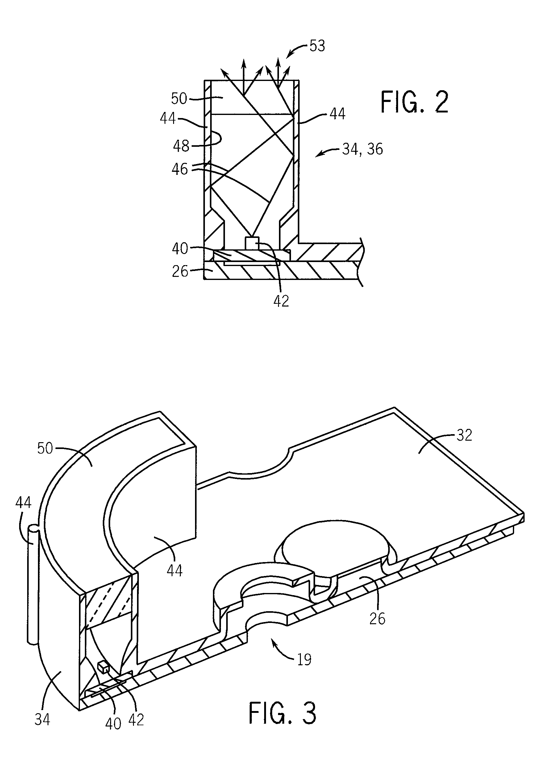
[0044]Referring now to FIGS. 2 and 3, the molded lamp housing 32 may fit against the top of the printed circuit board 26 and provides upwardly extending arcuate chambers 34 and 36 together defining an arc extending slightly over 180° about axis 18 to surround the periphery of the knob 14. Chamb...


PUM


Abstract

An illuminated control for a gas range or the like provides arcuate reflective chambers capped by diffusers to create a substantially continuous glowing circular sector indicating the status of a possibly low visibility gas flames. Line power may be used for direct drive of light emitting diodes illuminating the reflective chambers through the use of discrete series-connected voltage dropping resistors distributed to prevent heat concentration.

Description

CROSS-REFERENCE TO RELATED APPLICATIONS[0001]This application claims the benefit of U.S. provisional application 60 / 975,358 filed Sep. 26, 2007 hereby incorporated by reference.STATEMENT REGARDING FEDERALLY SPONSORED RESEARCH OR DEVELOPMENT--BACKGROUND OF THE INVENTION[0002]The present invention relates to controls for household appliances and in particular for control providing a visual indication of the setting of the control.[0003]Dial controls, for example, those used on a cook top, provide an operator (such as a knob) for controlling the heat setting of the burners of the cook top. Most simply, the position of the knob provides a visual indication to the user of the particular setting selected by the user.[0004]Sometimes it may be desirable to provide an electronic display indicating the state of a burner apart from the position of the dial control. For example, a light may be used to indicate that the burner is in simmer mode on a gas-stove top when this might not be apparent ...

Claims


Application Information

Patent Timeline
Patent Type & Authority Patents(United States)
IPC IPC(8): F21V23/04
CPCG05G1/105G01D11/28F24C3/126
Inventor CLAPROOD, EDWARD J.
Owner ILLINOIS TOOL WORKS INC
Learn More