
Vehicle motor control apparatus

a technology for controlling apparatus and motors, applied in the direction of motor/generator/converter stopper, electronic commutator, dynamo-electric converter control, etc., can solve the problem of increasing torque ripple, reduce torque ripple, accelerate and smoothly raise the rotation speed of the engine

Inactive Publication Date: 2011-04-19
MITSUBISHI ELECTRIC CORP
View PDF8 Cites 4 Cited by
  • Summary
  • Abstract
  • Description
  • Claims
  • Application Information

AI Technical Summary

Benefits of technology

[0006]The present invention has been implemented in order to solve the foregoing problems; the objective thereof is to provide a vehicle motor control apparatus capable of enhancing the average output torque of a motor and reducing the torque ripple so as to rapidly and smoothly raise the rotation speed of an engine up to a high speed when the engine is restarted.
[0007]Another objective thereof is to provide a vehicle motor control apparatus that can reduce harmonic components of electric currents that flow in the stator windings of a motor so as to decrease electromagnetic exciting force that causes an electromagnetic noise sound and electromagnetic noise, thereby reducing the noise sound of the motor, which is caused by the electromagnetic exciting force.
[0009]In a vehicle motor control apparatus according to the present invention, the q-axis current, out of the currents that flow the stator windings of a motor, which has a large influence on the occurrence of torque, becomes large, whereby the average output torque of the motor can be enhanced. Moreover, because the current waveform becomes similar to a sinusoidal wave, fluctuation in the q-axis current decreases; therefore, the torque ripple can be reduced. As a result, it is made possible to raise the rotation speed of an engine up to a high speed when the engine is restarted, whereby the engine can rapidly and smoothly be restarted.
[0010]Still moreover, because the current waveform becomes similar to a sinusoidal wave and harmonic components decrease, electromagnetic exciting force that causes an electromagnetic noise sound and electromagnetic noise can be reduced; therefore, the noise sound of the motor, caused by electromagnetic exciting force, can be reduced.

Problems solved by technology

Moreover, for the above reason, there has been a problem that the low-speed rotation (the 120-degree rectangular wave energization method) makes the current waveform rectangular and causes the torque ripple to increase.

Method used


Image

  • Vehicle motor control apparatus
  • Vehicle motor control apparatus
  • Vehicle motor control apparatus

Examples


embodiment 1

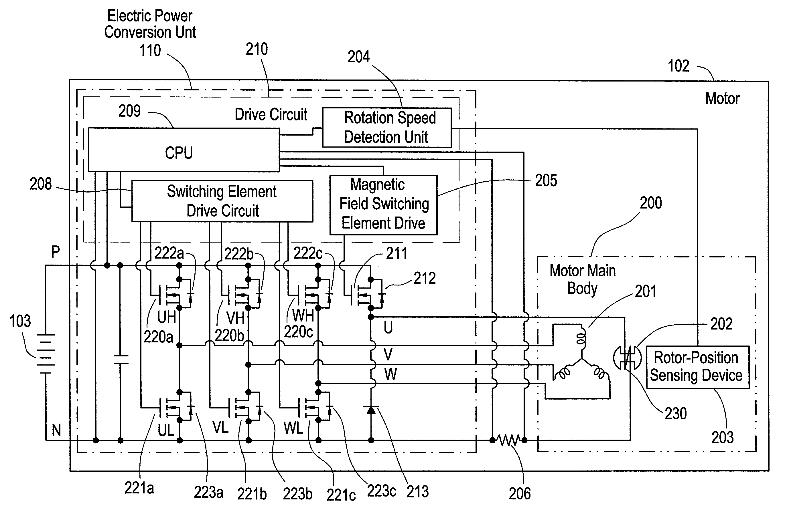
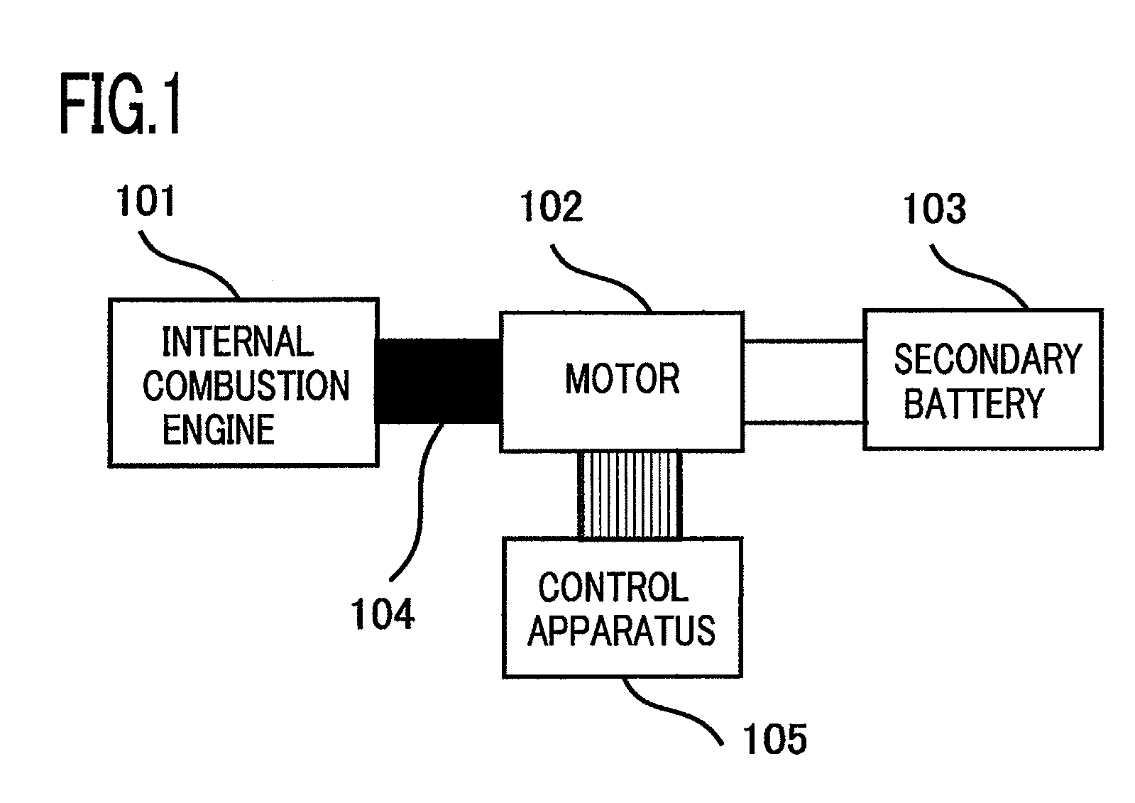
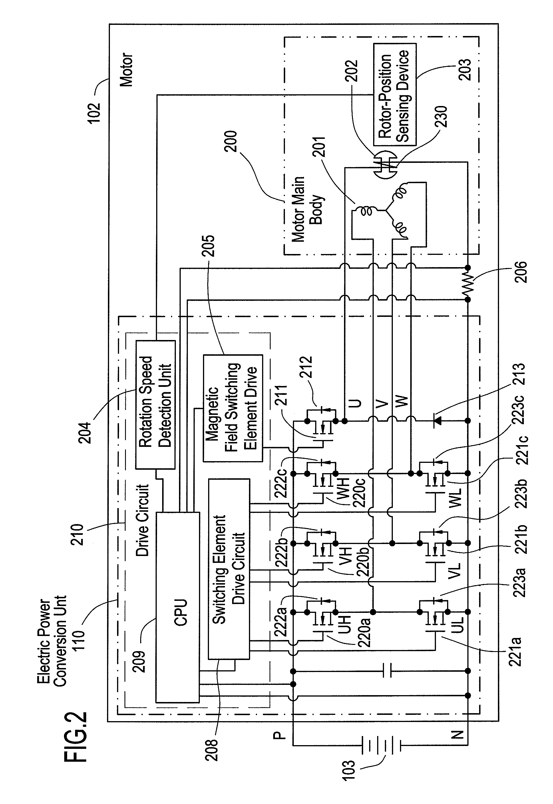
[0019]FIG. 1 is a conceptual configuration diagram in the case where a vehicle motor control apparatus or a power-generation motor control apparatus according to Embodiment 1 of the present invention is applied to a vehicle. In FIG. 1, reference numeral 101 denotes an internal combustion engine such as a gasoline engine or a diesel engine; reference numeral 102 denotes a motor that is coupled with the internal combustion engine 101 directly or via a coupling means 104 such as a belt or a pulley and disposed in such a way as to be able to transfer torque to and receive torque from the internal combustion engine 101; reference numeral 103 denotes a secondary battery that is electrically connected to the motor 102; the secondary battery 103 may be a secondary battery that is utilized also for other vehicle loads or a secondary battery dedicated to the motor 102. The secondary battery 103 may be a capacitor, and the motor 102 may be a power-generation motor. Reference numeral 105 is a c...


PUM


Abstract

There is provided a vehicle motor control apparatus that alternately switches a first ON state in which one of the stator winding terminals is energized through an upper switch element group and another stator winding terminal is energized through a lower switch element group and a second ON state in which one of the stator winding terminals is energized through one of the upper switch element group and the lower switch element group and two other stator winding terminals are energized through the other switch element group, in one cycle period of an electric angle that changes as the rotor rotates.

Description

BACKGROUND OF THE INVENTION[0001]1. Field of the Invention[0002]The present invention relates to a vehicle motor control apparatus for controlling the drive of a motor that is mounted on a vehicle and coupled with the engine, and more particularly to a vehicle motor control apparatus capable of raising the average torque so as to activate an engine rapidly and smoothly when the engine is restarted.[0003]2. Description of the Related Art[0004]Japanese Patent Laid-Open Pub. No. 2004-129379 discloses a conventional control apparatus for controlling the drive of a vehicle motor that is coupled with an engine. The control apparatus disclosed in Japanese Patent Laid-Open Pub. No. 2004-129379 utilizes a control method in which, when an engine is started, a method of energizing the respective phase of stator windings of the motor is switched from a 120-degree rectangular wave energization method to a 180-degree rectangular wave energization method.[0005]In the motor control apparatus disclo...

Claims


Application Information

Patent Timeline
Patent Type & Authority Patents(United States)
IPC IPC(8): H02P6/14H02P6/06H02P6/08H02P6/32H02P9/04
CPCH02P6/001H02P6/08H02P6/10H02P9/04H02P6/16H02P6/165H02P6/145H02P6/153H02P6/17H02P6/34
Inventor FUJITA, MASAHIKO
Owner MITSUBISHI ELECTRIC CORP
Learn More