Electro-optic display

a display and optical technology, applied in the field of visual displays, can solve the problems of flickering of the display, consequent eye strain of the viewer, and the inability of the gyricon technology to produce image quality comparable to that of images printed on paper, and achieve the effects of reducing the aspect ratio, good fill factor, and structural stability

Inactive Publication Date: 2011-04-19
FANTASY SHINE LTD +1
View PDF63 Cites 12 Cited by
  • Summary
  • Abstract
  • Description
  • Claims
  • Application Information

AI Technical Summary

Benefits of technology

[0017]In some embodiments, the matrix has multiple channels connecting multiple cells along the path. For example, these channels can be substantially parallel to one another and can be connecting cells in rows. In other embodiments the channels may be intersecting, e.g., they can be substantially perpendicular to each other. Preferably, these channels are arranged so as to allow the dielectric fluid to be drawn into the front plane during its assembly. In one example, at least some of the channels have a cross sectional area of at least about 5% of the cross sectional area of the cell. In some embodiments the walls of the cells are comprised of “posts”, and the fluid is allowed to flow freely in the channels between the posts. In some embodiments, the matrix is designed such that at least one cell in the matrix is in fluid communication with each of its adjacent cells. In some embodiments the matrix includes a plurality of regions, wherein the cells within the same region are in fluid communication with one another, and the cells from different regions are separated from one another by a wall preventing fluid communication between adjacent regions of the matrix. For example, a wall can separate regions every 2-100 (e.g., every 5-50) rows of cells. Such matrix design minimizes the chances for failure of the display.
[0019]In some embodiments, the matrix is designed such that the height of the cells allows for a translational movement of an optically anisotropic element in a cell in a direction defined by the first and second sides of the front plane (typically to the viewer and away from the viewer). For example, the height of the cell may be at least 1.1 (e.g., 1.5) times greater than the height or a diameter of an optically anisotropic element residing in a cell.
[0022]In other embodiments, it is advantageous to use a square close pack design in a matrix. The square pack design can achieve a good fill factor and can also make use of the walls with a lower aspect ratio. Therefore such design can be more easily manufactured, and can be structurally more stable than a hexagonal design having high aspect ratio walls. In some embodiments, the walls (e.g., posts) of a matrix in a square pack design have an aspect ratio of less than about 5:1, e.g., about 4:1.

Problems solved by technology

While low refresh rates can conserve some power, this often results in flickering of the display and consequent eye strain of the viewer.
Gyricon technology, however, failed to produce image quality comparable to that of images printed on paper.
In particular, gyricon displays did not possess the high reflectance of white paper, therefore providing low-contrast images.
Gyricon displays also had limited environmental stability, because plasticized polymer was not capable of withstanding high-temperature or high-humidity conditions.
Further, only few dielectric fluids were suitable for use in gyricon displays, since dielectric fluid in gyricon was serving both as a polymer plasticizer and as a rotation media and therefore had to possess properties suitable for both of these applications.
Even in a closely packed monolayer there remains some elastomer or matrix material occupying gaps between the spheres, which reduces the observed reflectance of the display and, hence, the contrast and brightness of displayed images.
Such a matrix, although useful as a holding and aligning element, does not address the problem of low reflectance in the areas between the spheres, and, consequently, does not improve the contrast and brightness of the display.
The coating typically imparts an electrical charge to the elements, and thus creates electrical anisotropy.

Method used


Image

  • Electro-optic display
  • Electro-optic display
  • Electro-optic display

Examples


Embodiment Construction

[0061]Introduction and Overview

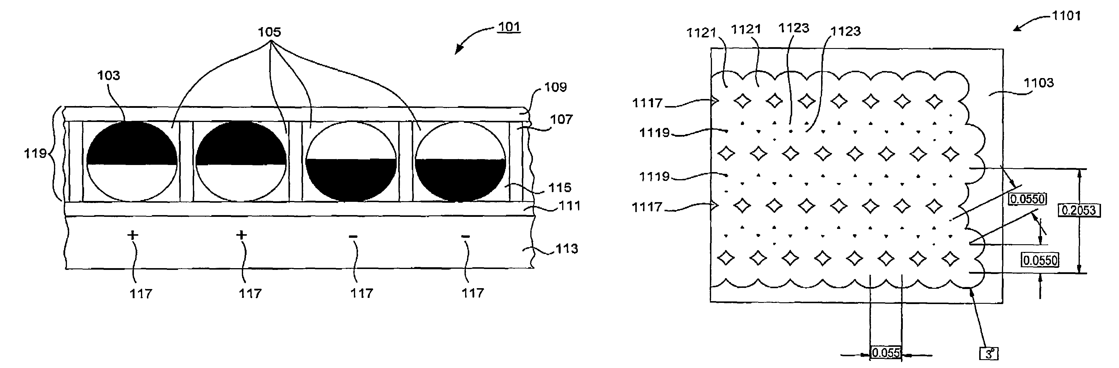
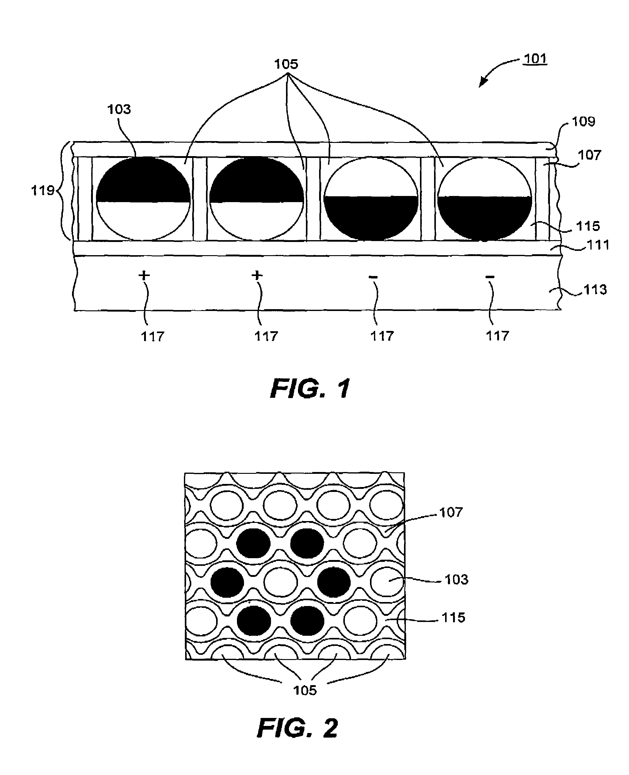
[0062]Electro-optic displays of present invention may possess a number of advantageous characteristics that may compare favorably to gyricon electronic paper. These displays may provide high brightness and contrast images (due, for example, to specific properties of the matrix). They also may possess high resolution due to, for example, small pixel size. Further, the displays of present invention may be manufactured from environmentally robust materials, resulting in environmentally stable displays (e.g., displays withstanding high temperature and high humidity conditions). The design of these displays allows for easy display manufacturing, making use, in certain embodiments of a channel in the matrix during display assembly. Display assembly methods are also provided in some aspects of present invention.

[0063]The simplicity of electro-optic displays provided by this invention minimizes the number of components, and thus cost of display manufacturing. ...


PUM

PropertyMeasurementUnit
white reflectanceaaaaaaaaaa
diameteraaaaaaaaaa
diameteraaaaaaaaaa

Abstract

An electro-optic display includes a “matrix” for confining moving elements of the display (e.g., rotating or twisting elements). The matrix (or at least the viewable portions thereof) may have a high reflectivity, comparable to that of white paper. This results in an overall “whiter” or brighter display. The matrix may include channels to facilitate inter-cell fluid transport and high-density element packing. In some cases, the matrix elements provide a hexagonal arrangement of cells for holding the rotating elements. The rotating elements of the display may be electrically and optically anisotropic hemispherically coated spheres. The hemispherical coating typically provides the necessary charge to create electrical anisotropy.

Description

CROSS-REFERENCE TO RELATED APPLICATIONS[0001]This application claims priority under 35 USC 119(e) from U.S. Provisional Patent Application No. 60 / 850,883 naming Lipovetskaya et al. as inventors, titled “Electro-Optic display” filed Oct. 10, 2006, which is incorporated by reference in its entirety and for all purposes.FIELD OF THE INVENTION[0002]The present invention relates to visual displays. Specifically, it relates to electro-optic displays. More specifically, it relates to front plane designs for electro-optic displays.BACKGROUND OF THE INVENTION[0003]Visual displays that make use of ambient light to illuminate their pixels (reflective) and that produce an image that is indefinitely stable in the absence of electrical input are often referred to as electronic paper, since they mimic some of the most advantageous properties of paper. Just like white paper that reflects and scatters incident light and does not require additional light sources for viewing the images printed upon it...

Claims


Application Information

Patent Timeline
Patent Type & Authority Patents(United States)
IPC IPC(8): G02B26/00
CPCG02B26/026Y10T29/49002Y10T137/0391
Inventor LIPOVETSKAYA, YELENAGOBROGGE, BRIAN
Owner FANTASY SHINE LTD
Why Eureka
Try Eureka