Water wave-based energy transfer system

a technology of energy transfer system and water wave, which is applied in the direction of water power plant, machine/engine, electric generator control, etc., can solve the problems of large-scale frameworks, built or deployed in the ocean, difficult and costly construction, and high construction cost, and achieve the effect of multiplication of the useful work possible on shor

Inactive Publication Date: 2011-04-26
BROWN CLIFFORD H
View PDF19 Cites 8 Cited by
  • Summary
  • Abstract
  • Description
  • Claims
  • Application Information

AI Technical Summary

Benefits of technology

[0010]A plurality of buoyant floats may be provided, with all of the floats preferably being joined to separate anchors. The plurality of floats are preferably staggered in a line towards the shore, as will be described below. The plurality of buoyant floats are joined to the tensioning mechanism by a single secondary cable. The oscillatory motion of the at least one buoyant float caused by the water waves generates oscillatory motion in the second cable, which, in turn, drives the power conversion mechanism coupled with the tensioning mechanism to create energy, such as electricity, for useful work. If the distance between the most distance float (measured from the shore) and the nearest float is less than the wavelength of incoming waves, multiple reciprocal horizontal motions can be produced during the passing of a single wave, thus multiplying the useful work possible on shore.

Problems solved by technology

However, such systems typically require the construction of large and complex structures within the ocean.
Not only are such structures difficult and costly to build, but their large-scale frameworks, built or deployed within the ocean, are vulnerable to storm damage and are costly to maintain.

Method used


Image

  • Water wave-based energy transfer system
  • Water wave-based energy transfer system
  • Water wave-based energy transfer system

Examples


Embodiment Construction

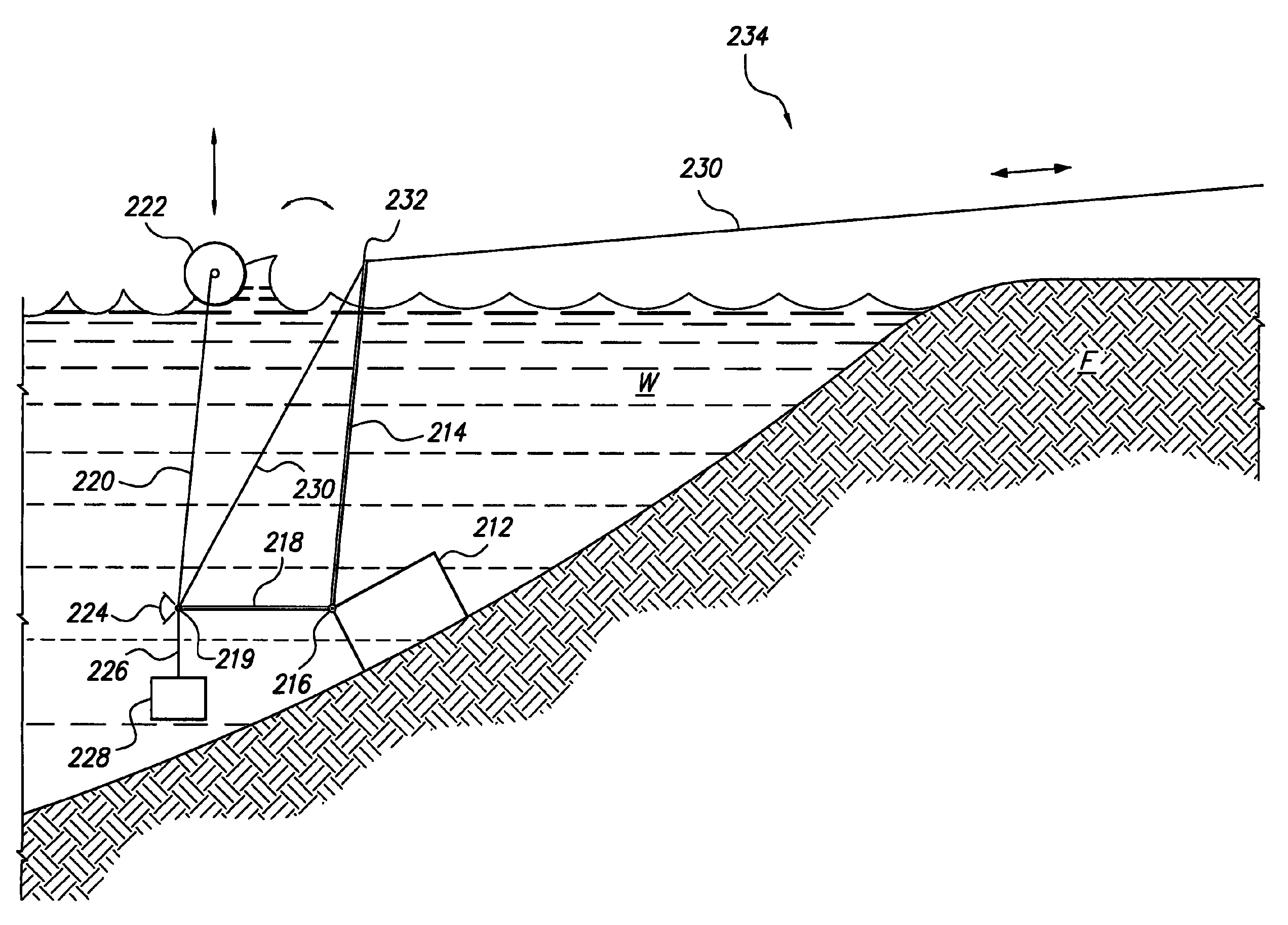
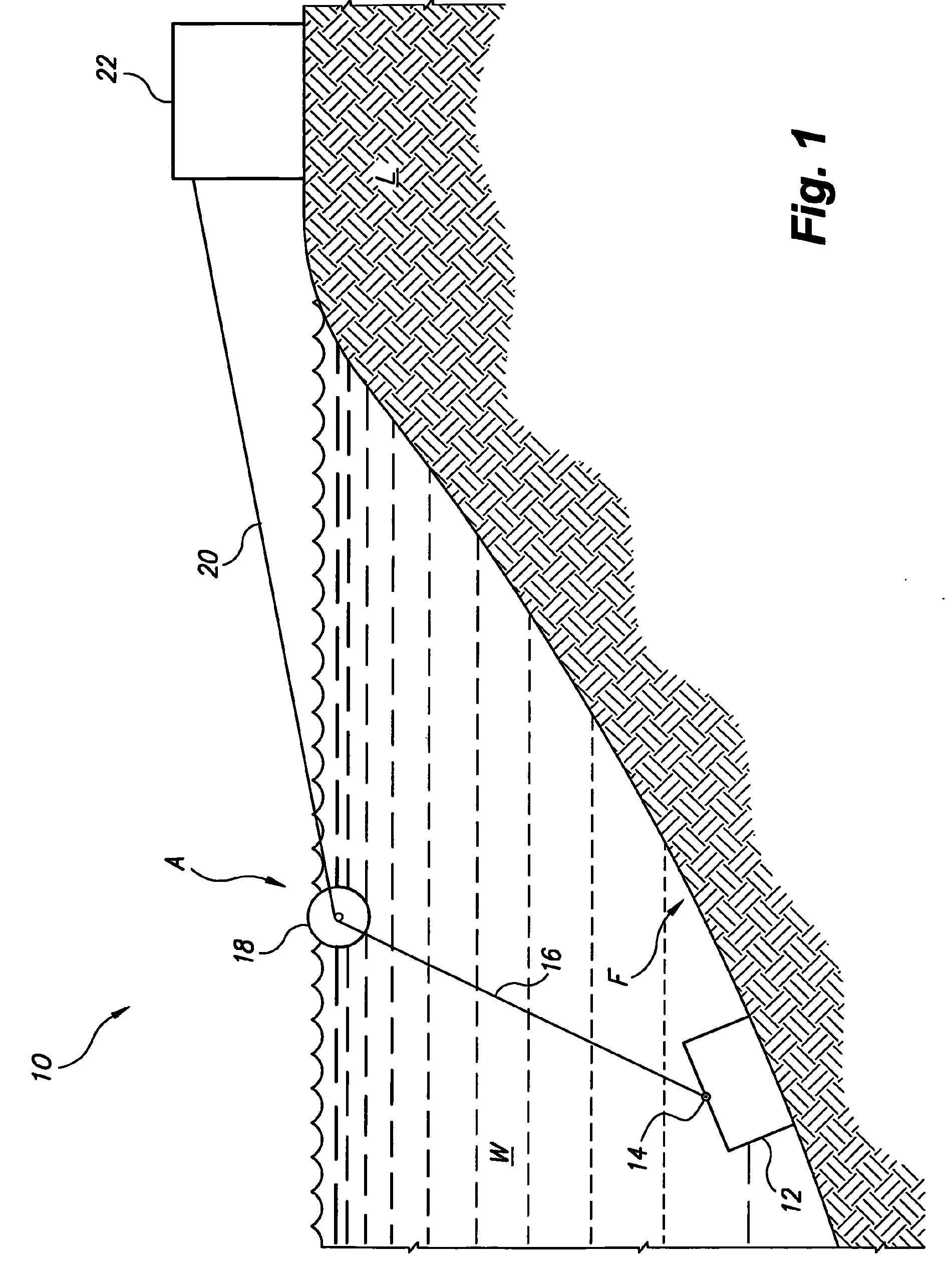
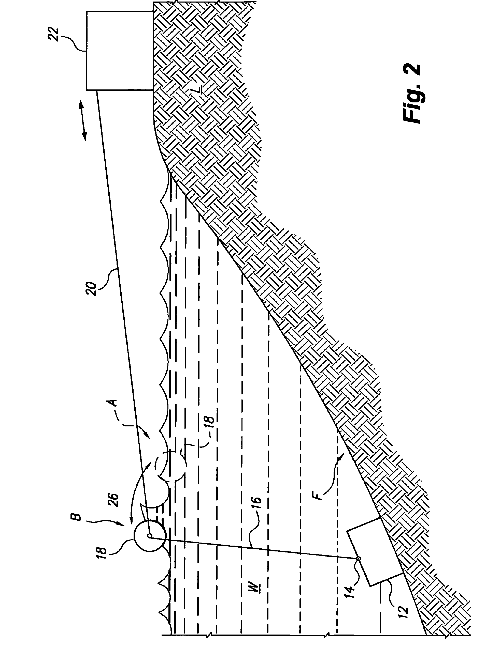
[0021]The present invention is directed towards a water wave-based energy transfer system, designated generally as 10 in the drawings. As shown in FIGS. 1 and 2, the water wave-based energy transfer system 10 is a system for generating useful work from the natural motion of water waves, such as ocean waves. The system includes an anchor 12 adapted for stationary lodgment on an underwater support surface, such as the ocean floor F. At least one buoyant float 18 is provided for floating either on or below the ocean surface (shown in initial position A in FIG. 1). It should be understood that the system may be utilized with any body of water W and that the ocean and shore illustrated in the drawings is shown for exemplary purposes only.

[0022]At least one primary cable 16 joins the at least one buoyant float 18 to the upper end of anchor 12, and a secondary cable 20 joins the at least one buoyant float 18 to a tensioning mechanism 22 located on the shore (or other dry land mass) L. Alth...


PUM


Abstract

The water wave-based energy transfer system is a system for generating electrical power from the natural motion of water waves, such as ocean waves. The system includes an anchor adapted for stationary lodgment on an underwater support surface, such as the ocean floor, and at least one buoyant float provided for floating either on or below the ocean surface. At least one primary cable joins the at least one buoyant float to the anchor, and a secondary cable joins the at least one buoyant float to a tensioning device coupled with a power conversion and generation device on the shore. The oscillatory motion of the at least one buoyant float caused by the water waves or swells generates oscillatory motion in the second cable, which drives the power conversion and generation device.

Description

CROSS-REFERENCE TO RELATED APPLICATION[0001]This application claims the benefit of U.S. Provisional Patent Application Ser. No. 60 / 996,431, filed Nov. 16, 2007.BACKGROUND OF THE INVENTION[0002]1. Field of the Invention[0003]The present invention relates to devices and systems for the transfer of mechanical forces derived from water waves to a location where they can be converted into, for example, electrical energy, or perform other useful work. More particularly, the invention is directed towards a water wave-based energy transfer system that converts the vertical motion of water waves into substantially horizontal motion, which can then be transferred a considerable distance and harnessed to provide useful work in a manner that minimizes construction costs and reduces the complexity of the elements exposed to water.[0004]2. Description of the Related Art[0005]Due to the limitations of non-renewable energy sources, such as oil and coal, as well as the negative environmental effects...

Claims


Application Information

Patent Timeline
Patent Type & Authority Patents(United States)
IPC IPC(8): F03B13/18F03B17/02
CPCE02B9/08F03B13/1885F03B13/188Y02E10/38Y02E10/30
Inventor BROWN, CLIFFORD H.
Owner BROWN CLIFFORD H
Why Eureka
Try Eureka