
Bicycle sprocket apparatus with a chain support structure

a technology of chain support and bicycle sprocket, which is applied in the direction of bicycle equipment, gearing, hoisting equipment, etc., can solve the problems of increasing the number of parts that must be assembled, increasing the cost of the wheel assembly, and affecting the safety of the wheel protector

Inactive Publication Date: 2011-04-26
SHIMANO INC
View PDF31 Cites 53 Cited by
  • Summary
  • Abstract
  • Description
  • Claims
  • Application Information

AI Technical Summary

Benefits of technology

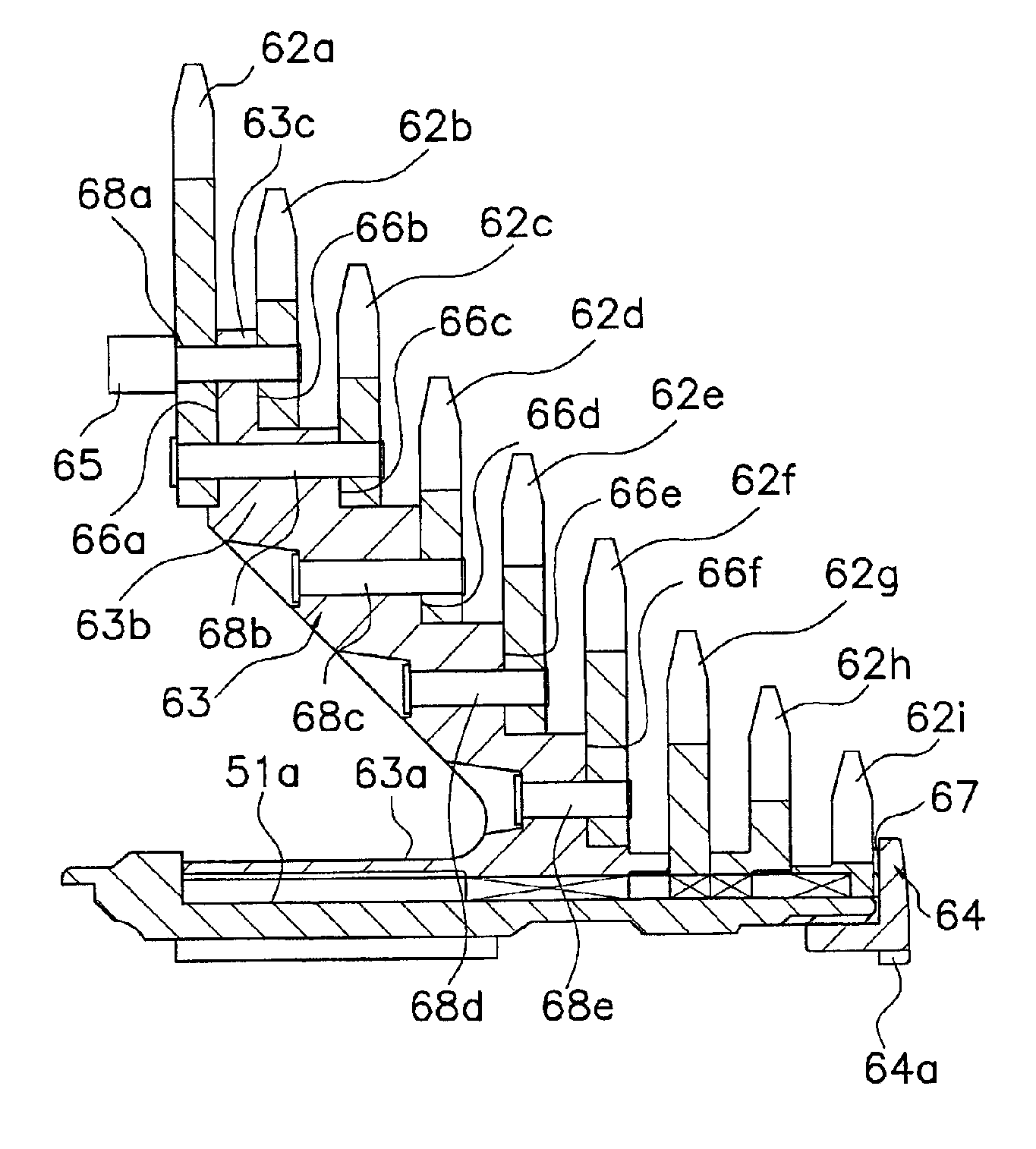
The present invention is about a bicycle sprocket assembly with various features. The assembly includes a sprocket mounting member, a first sprocket, and a second sprocket. The mounting member has a hub mounting portion and a sprocket mounting portion, with the first sprocket mounted on the first mounting surface and the second sprocket mounted on the second mounting surface. A fastener fastens the first sprocket to the first mounting surface, and a chain supporting structure extends from the fastener in a first direction away from the side surface of the first sprocket that faces in the first direction. The assembly also includes a first sprocket that forms a chain support member that projects in the first direction away from a side surface of the first sprocket that faces in the first direction, and an innermost peripheral surface of the first sprocket is disposed radially outwardly from the inner peripheral surface of the hub mounting portion. These features provide improved performance and efficiency of the bicycle sprocket assembly.

Problems solved by technology

If the chain accidentally derails axially inwardly from the largest-diameter sprocket and drops toward the rear wheel hub, a nearby spoke may be damaged.
Unfortunately, the spoke protector increases the number of parts that must be assembled to form the wheel assembly.
The spoke protector also increases the cost of the wheel assembly.

Method used


Image

  • Bicycle sprocket apparatus with a chain support structure
  • Bicycle sprocket apparatus with a chain support structure
  • Bicycle sprocket apparatus with a chain support structure

Examples


Embodiment Construction

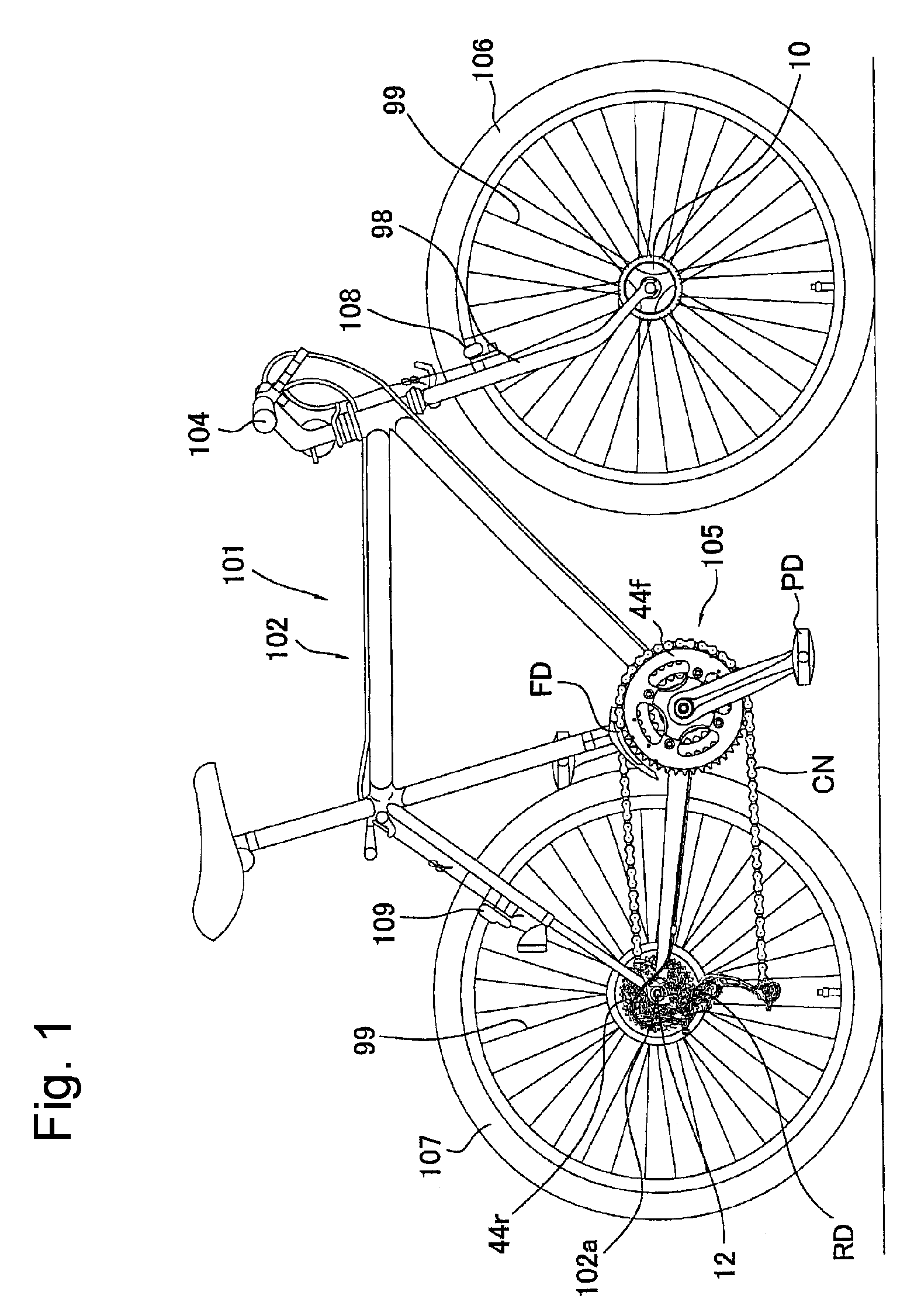
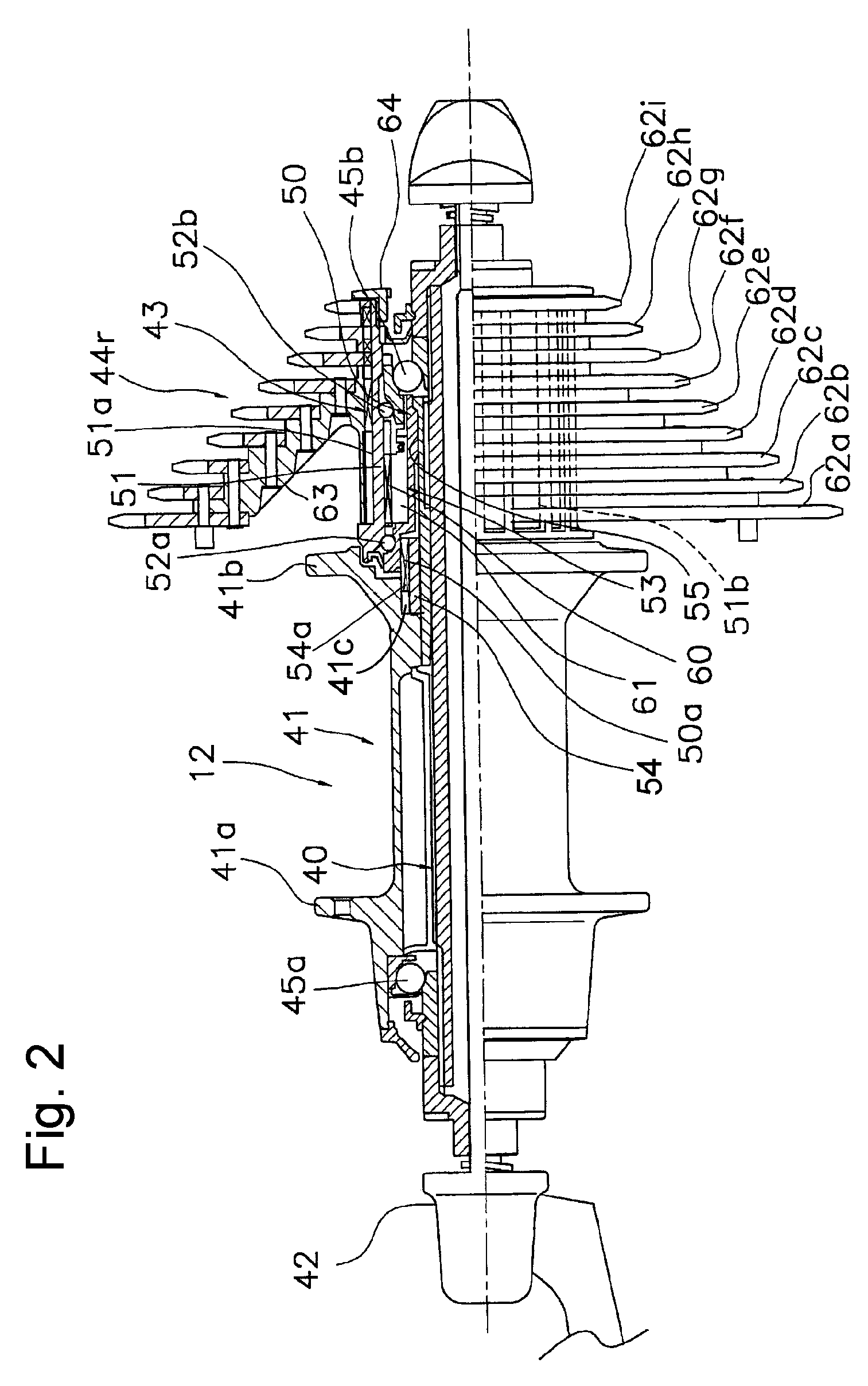
[0023]FIG. 1 is a side view of a particular embodiment of a bicycle 101. Bicycle 101 is a mountain bicycle comprising a diamond-shaped frame 102, a front fork 98 rotatably mounted to frame 102, a handlebar assembly 104 mounted to the upper part of fork 98, a front wheel 106 including spokes 99 and a front hub 10 rotatably attached to the lower part of fork 98, a rear wheel 107 including spokes 99 and a rear hub 12 rotatably attached to a pair of rear dropouts 102a of frame 102, and a drive unit 105. A front wheel brake 108 is provided for braking front wheel 106, and a rear wheel brake 109 is provided for braking rear wheel 107. Drive unit 105 comprises a chain CN, a front sprocket assembly 44f coaxially mounted with a crank having pedals PD, a front derailleur FD attached to a seat tube of frame 102, a rear sprocket assembly 44r coaxially mounted with rear wheel 107, and a rear derailleur RD.

[0024]As shown in FIG. 2, rear hub 12 includes a hub shaft 40 that detachably mounts to rea...


PUM


Abstract

A bicycle sprocket apparatus comprises a sprocket mounting member, a first sprocket, and a second sprocket. The sprocket mounting member includes a hub mounting portion and a sprocket mounting portion, wherein the hub mounting portion is structured to be mounted to a rotating hub that rotates around a rotational axis. The sprocket mounting portion includes a first sprocket mounting surface that faces in a first direction and a second sprocket mounting surface that faces in an opposite second direction. The first sprocket is disposed at the first sprocket mounting surface, and the second sprocket is disposed at the second sprocket mounting surface. A fastener fastens the first sprocket to the first sprocket mounting surface, and a chain supporting structure extends from the fastener in the first direction and projects in the first direction away from a side surface of the first sprocket that faces in the first direction.

Description

BACKGROUND OF THE INVENTION[0001]The present invention is directed to bicycle sprocket assemblies and, more particularly, to a bicycle sprocket assembly that has a chain support structure.[0002]A bicycle sprocket assembly may comprise, for example, a plurality of chain-engaging sprockets attached to a freewheel assembly mounted together with a rear wheel hub. The smallest-diameter sprocket having the least number of teeth usually is positioned on the axially outermost side, and the largest-diameter sprocket having the greatest number of teeth is positioned on the axially innermost side. A rear derailleur typically is mounted in close proximity to the sprocket assembly for switching a bicycle chain among the plurality of sprockets.[0003]In such a sprocket assembly, the largest-diameter sprocket is mounted close to the spokes of the rear wheel. If the chain accidentally derails axially inwardly from the largest-diameter sprocket and drops toward the rear wheel hub, a nearby spoke may ...

Claims


Application Information

Patent Timeline
Patent Type & Authority Patents(United States)
IPC IPC(8): F16H55/30B62M9/10
CPCB62M9/10
Inventor TOKUYAMA, KOJI
Owner SHIMANO INC
Learn More