Handheld cleaning appliance

a cleaning appliance and handheld technology, applied in the field of cleaning appliances, can solve the problems of a small amount of dirt and dust passing through the separating apparatus and being carried to the airflow generator, affecting the operation of the cleaning machine, and affecting the cleaning effect, so as to achieve the effect of enduring greater wear and tear

Inactive Publication Date: 2011-04-26
DYSON TECH LTD
View PDF19 Cites 175 Cited by
  • Summary
  • Abstract
  • Description
  • Claims
  • Application Information

AI Technical Summary

Benefits of technology

[0009]It is an object of the present invention to provide a cleaning appliance having an improved interlock which is able to prevent operation of an airflow generator if a pre-motor filter is missing from, or incorrectly located in, the cleaning appliance. It is a further object of the present invention to provide a cleaning appliance having an interlock which is less susceptible to clogging or blocking, and which is less prone to mechanical failure.
[0011]By providing an interlock having first and second parts which communicate remotely, the second part which is located on the main body can be isolated from the airflow path. This means that the second part will not be subject to dirt and dust in the airflow and will be less likely to become dirty or damaged. The wall delimiting the flowpath protects the second part of the interlock and prevents contamination of the second part by dirt and dust which may be present in the flowpath.
[0012]Preferably, the first and second parts are spaced from one another when the filter is correctly located in the pre-determined position. By providing such an arrangement, direct contact between the first and second parts is avoided. This reduces mechanical wear and tear and consequently improves reliability.
[0013]Preferably, the interlock is adapted and arranged to prevent operation of the airflow generator when the separation between the first and second parts exceeds a pre-determined distance. This arrangement allows the interlock to operate as a remote switch in which mechanical contact between the two parts is unnecessary.
[0014]Preferably, the filter has a longitudinal axis and a transverse axis and the first part is spaced from at least one of the longitudinal and transverse axes. More preferably, the first part is spaced from both the longitudinal axis and the transverse axis. This prevents the airflow generator from operating if the filter is located back-to-front or upside down in the cleaning appliance.
[0015]Preferably, the first part includes an emission source and the second part includes a detector. More preferably, the first part includes a passive emission source. By providing such an arrangement, the first part can be a passive element that does not require a power source and can withstand greater wear and tear.

Problems solved by technology

Irrespective of the type of separating apparatus used, there may be a risk of a small amount of dirt and dust passing through the separating apparatus and being carried to the airflow generator.
It is undesirable for dirt and dust particles to pass through the fan of an airflow generator because the fan may become damaged or may operate less efficiently.
During normal operation of a vacuum cleaner, fine dirt and dust may be deposited on a pre-motor filter and, after a period of time, it could become blocked.
Blockages reduce the efficiency at which a vacuum cleaner operates.
Once the pre-motor filter has been removed, there is a risk that a user will not replace the pre-motor filter, or will replace it incorrectly.
If the vacuum cleaner is operated without the pre-motor filter or with it fitted incorrectly, then there is a risk of the dirt and dust which would normally be captured by the pre-motor filter causing damage to, or failure of, the airflow generator as discussed previously.
However, when the filter is not fitted correctly, the projection does not engage with the switch and the vacuum cleaner will not operate.
Therefore, there may be a risk that these parts will become clogged with dirt and dust over time, or be prone to mechanical failure.

Method used


Image

  • Handheld cleaning appliance
  • Handheld cleaning appliance
  • Handheld cleaning appliance

Examples


Embodiment Construction

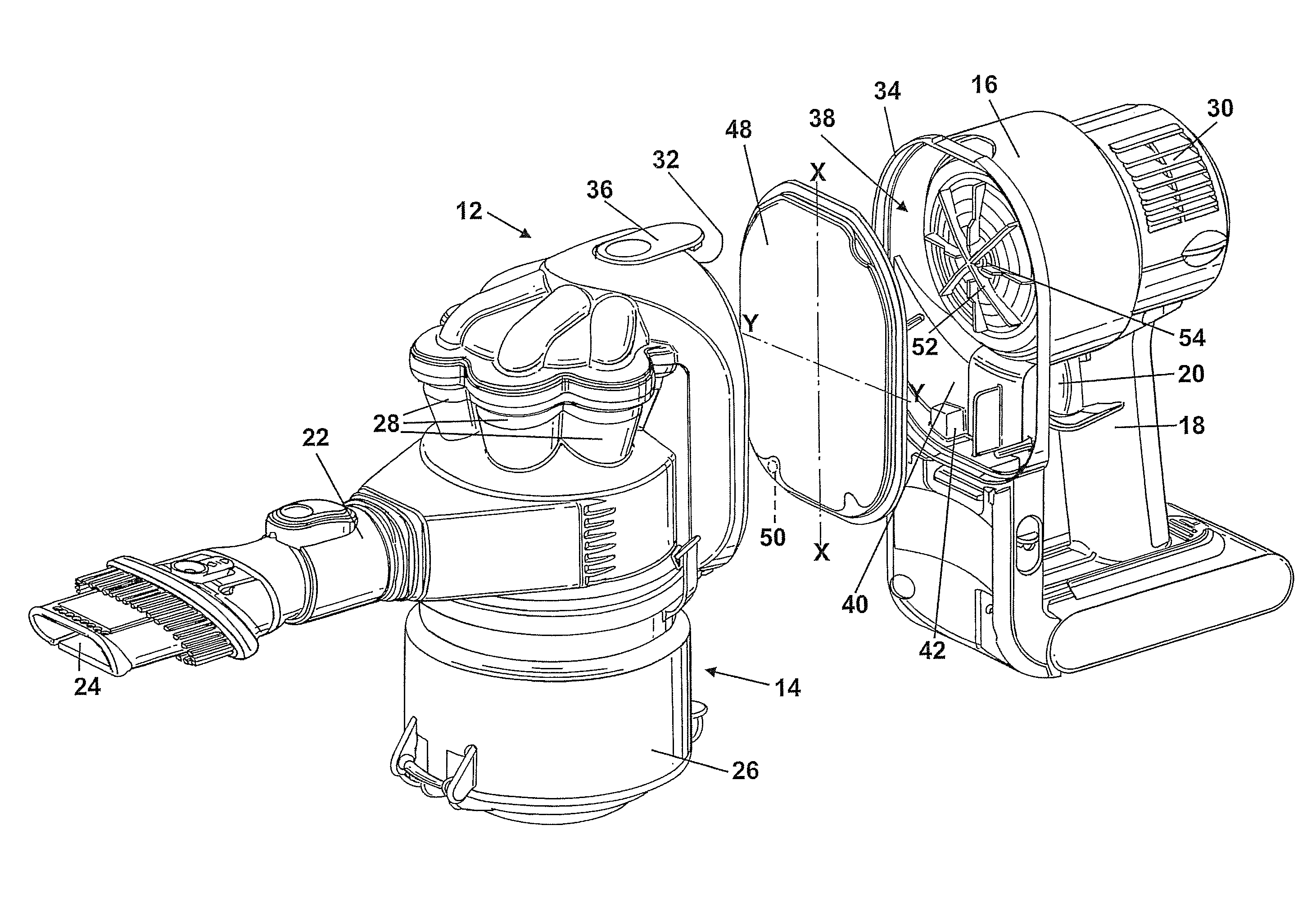
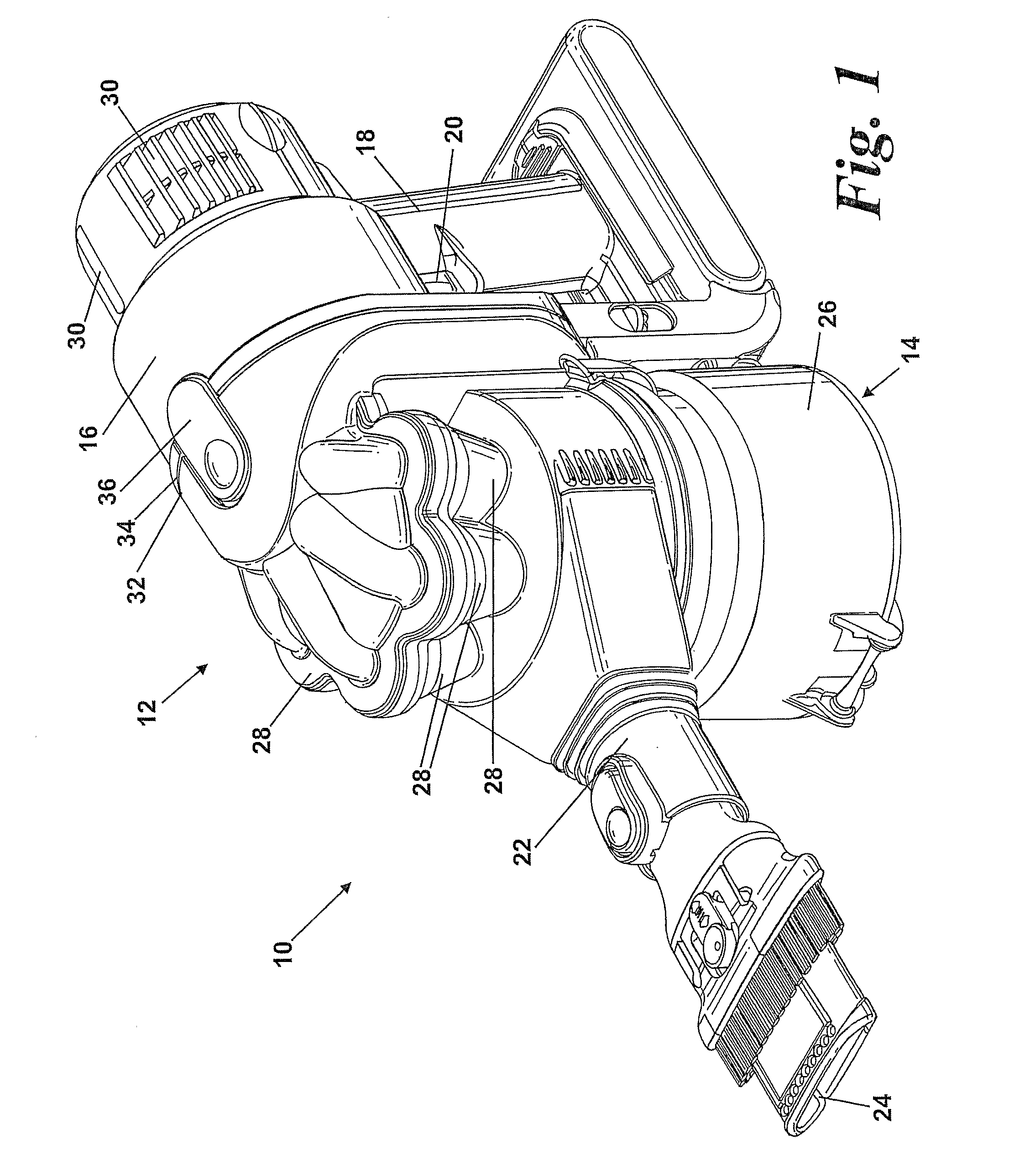
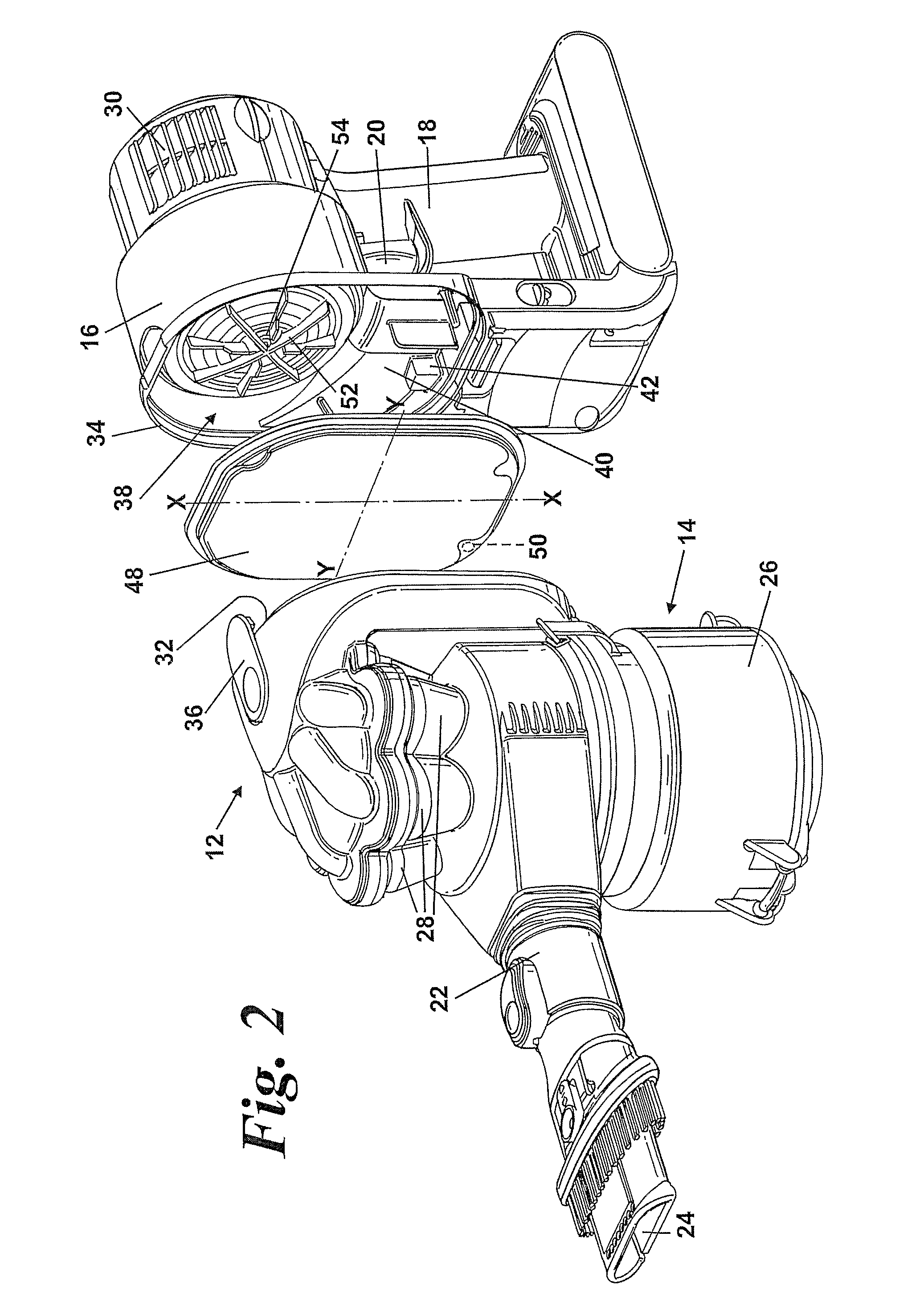
[0020]FIG. 1 shows a hand-held vacuum cleaner 10. The hand-held vacuum cleaner 10 comprises a main body 12. The main body 12 includes cyclonic separating apparatus 14 which is capable of separating dirt and dust from an airflow, a motor housing 16 and a handgrip 18 for manipulating the hand-held vacuum cleaner 10 in use. The handgrip 18 includes a trigger 20 which is positioned such that it can be manipulated by a user's finger.

[0021]The main body 12 further includes a suction conduit 22 which has a suction opening 24 at one end. The suction conduit 22 communicates with the cyclonic separating apparatus 14. The cyclonic separating apparatus 14 comprises an upstream cyclone 26 and a plurality of downstream cyclones 28. A flowpath extends from the suction opening 24, through the suction conduit 22, the cyclonic separating apparatus 14 and the motor housing 16 to a plurality of exhaust vents 30 formed in the motor housing 16.

[0022]In FIG. 1, the cyclonic separating apparatus 14 is show...


PUM

PropertyMeasurementUnit
distanceaaaaaaaaaa
distanceaaaaaaaaaa
mechanical failureaaaaaaaaaa

Abstract

A cleaning appliance includes a main body, a filter and an interlock. The main body includes an airflow generator, a separating apparatus separating dirt and dust from an airflow, and a flowpath between the separating apparatus and the airflow generator delimited by a wall. The interlock has a first part located on the filter and a second part located on the main body outside the flowpath, arranged to communicate remotely when the filter is correctly located in the pre-determined position. The interlock is arranged selectively to allow or prevent operation of the airflow generator depending upon the relative separation between the first and second parts. By providing an interlock which has first and second parts which communicate remotely, the second part located on the main body can be isolated from the airflow path so that the second part is not subject to dirt and dust carried by the airflow.

Description

REFERENCE TO RELATED APPLICATIONS[0001]This application is a national stage application under 35 USC 371 of International Application No. PCT / GB2007 / 002526, filed Jul. 6, 2007, which claims the priority of United Kingdom Application No. 0614238.4, filed Jul. 18, 2006, the contents of which prior applications are incorporated herein by reference.FIELD OF THE INVENTION[0002]The invention relates to a cleaning appliance. Particularly, but not exclusively, the invention relates to a vacuum cleaner and more particularly to a hand-held vacuum cleaner.BACKGROUND OF THE INVENTION[0003]Vacuum cleaners are designed to separate dirt and dust from an airflow. Commonly, an airflow generator (for example, a motor and fan unit) generates an airflow which draws dirt- and dust-laden air into the vacuum cleaner through a dirty air inlet. The airflow then passes through a form of separating apparatus such as a porous bag or a cyclonic separator (see, for example, EP 0 042 723) to remove dirt and dust ...

Claims


Application Information

Patent Timeline
Patent Type & Authority Patents(United States)
IPC IPC(8): B01D50/00
CPCA47L5/24A47L9/122A47L9/19A47L9/2889A47L9/2894A47L9/2805Y10S55/03Y10S55/34A47L9/102A47L9/1666A47L9/16
Inventor OAKHAM, GEORGE FRANCIS PAUL
Owner DYSON TECH LTD
Why Eureka
Try Eureka