Stereolithographic method and apparatus

a stereolithographic and method technology, applied in auxillary shaping apparatus, manufacturing tools, additive manufacturing, etc., can solve the problems of high cost of uv laser system used as light source, high cost of stereolithographic apparatus of this type, and high labor intensity, and achieve high building accuracy, high building efficiency, and superior appearance and dimensional accuracy.

Active Publication Date: 2011-04-26
NABLESCO CORP
View PDF22 Cites 10 Cited by
  • Summary
  • Abstract
  • Description
  • Claims
  • Application Information

AI Technical Summary

Benefits of technology

[0013]The objective of the present invention is to provide a stereolithographic method and a stereolithographic apparatus, which enable manufacture of a high-quality, stereolithographic three-dimensional object at high building rate, with high building accuracy, and with superior productivity while preventing occurrence of variations in cure or strength even in the case of a large-size stereolithographic three-dimensional object, as well as in the case of a small-size or middle-size stereolithographic three-dimensional object. Particularly, the objective of the present invention is to provide a stereolithographic method and a stereolithographic apparatus, which enable manufacture of a high-quality, stereolithographic three-dimensional object at high building rate, with high building accuracy, and with superior productivity, wherein boundary areas among adjacent plotted areas in an optically-cured resin layer do not appear in the form of lines, streaks, or ridges in a finally-obtained stereolithographic three-dimensional object, and the three-dimensional object has unnoticeable boundary areas and superior appearance and dimensional accuracy.
[0014]Another objective of the present invention is to provide a stereolithographic method and a stereolithographic apparatus, which enable smooth manufacture of a high-quality, stereolithographic three-dimensional object having a high degree of building accuracy and being free from variations in cure and strength at high building rate without use of an expensive UV laser system even when an inexpensive light source, such as an ordinary UV lamp, is used.
[0015]The present inventors have conducted considerable research in order to attain the above-described objectives. At the time of manufacture of a stereolithographic three-dimensional object by means of exposing the surface of a photocurable resin composition to light by way of a planar plotting mask to thus sequentially form optically-cured resin layers having a predetermined cross-sectional profile pattern, the inventors have developed another technique in place of the above-described conventional technique of effecting exposure with the planar plotting mask remaining fixed or stationary. Specifically, according to the newly-developed technique, the planar plotting mask is continuously moved during exposure in at least one of the optical building processes, and building is performed upon exposure by means of continuously moving the planar plotting mask in synchronism with the continuous movement, to thus continuously change a mask image (a mask pattern) defined by the planar plotting mask in accordance with the predetermined cross-sectional profile pattern to be formed (building is effected upon exposure by means of continuously changing the mask image of the planar plotting mask as in the case of a motion picture; e.g., a movie or a TV screen). As a result, a stereolithographic three-dimensional object can be manufactured with high building accuracy, with high quality, at higher building rate, and with superior productivity as compared with the case of the conventional technique, while preventing occurrence of variations in cure even in the case of a large-size, stereolithographic three-dimensional object as well as in the case of a small-size or middle-size three-dimensional object.

Problems solved by technology

However, the above-described conventional method employing the spot-shaped UV laser beam is a so-called stippling method for forming a planar optically-cured pattern by means of radiating, in a moving manner; one spot-shaped laser beam onto the surface of a photocurable resin; and has problems of building involving consumption of much time and low productivity.
Moreover, a UV laser system used as the light source is extremely expensive, which makes the stereolithographic apparatus of this type expensive.
If the scan speed of the photo-mask is increased, an optically-cured section that is sufficiently cured cannot be formed on a per-line basis.
Moreover, this method is to form a planar optically-cured layer by means of making an optically-cured section one after another on a per-line basis, which involves consumption of much time for building the entire article.
Therefore, the building rate cannot be said to be sufficiently fast, and sufficient satisfaction cannot be achieved in view of productivity.
However, liquid-crystal masks (liquid-crystal shutters) or digital micromirror shutters, which realize such the high resolutions, are not currently available, or extremely expensive even if available.
Therefore, in the case of this method under which the planar plotting mask is fixedly arranged, difficulty is encountered, under the present circumstances, in manufacturing a large-size, stereolithographic three-dimensional object having an enhanced degree of accuracy (building accuracy), and the method can be applied solely to manufacture of a small-size stereolithographic three-dimensional object, in view of the degree of accuracy (building accuracy).
Therefore, under this method, exposure is performed not continuously but intermittently, and hence building speed becomes slow.
The cured state is likely to become discontinuous or non-uniform in a border between the sub-divided travel areas.
As a result, unevenness in the strength of the entire stereolithographic three-dimensional object, insufficient strength, unsatisfactory appearance, and a drop in dimensional accuracy are likely to arise.

Method used


Image

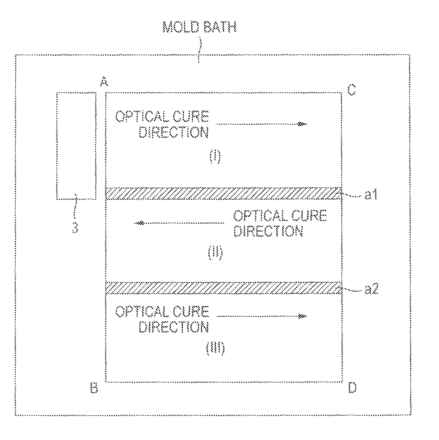
  • Stereolithographic method and apparatus
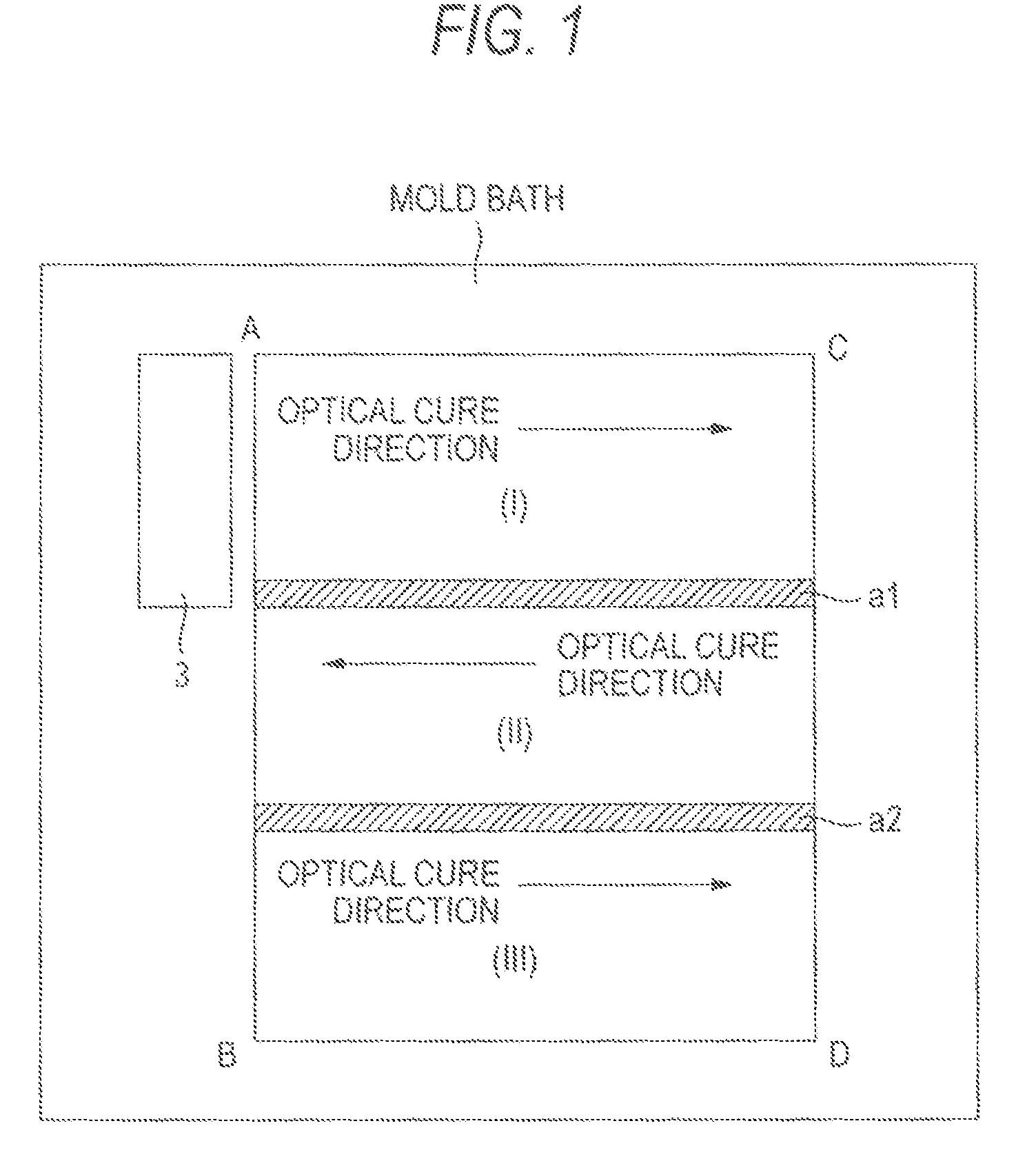
  • Stereolithographic method and apparatus
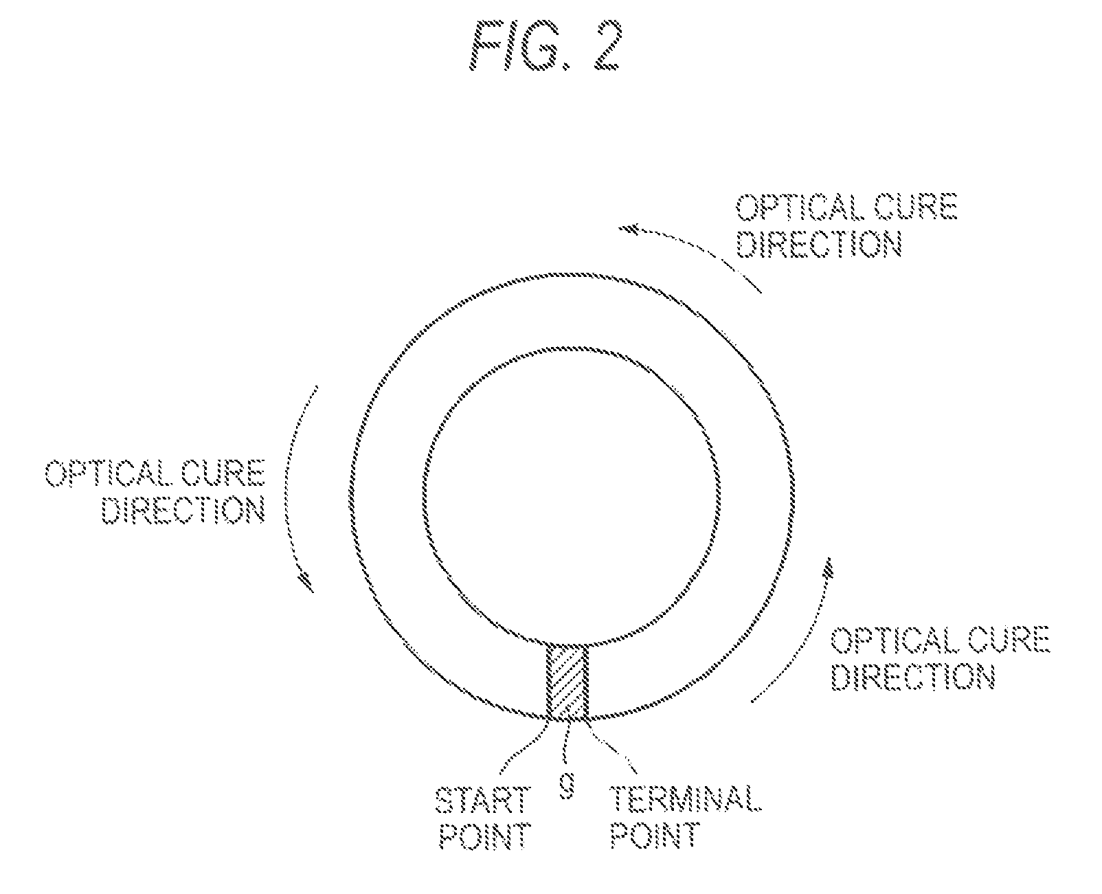
  • Stereolithographic method and apparatus

Examples


embodiments

[0108]The present invention will be described specifically hereinbelow by reference to the drawings. However, the present invention is not limited to the illustrated embodiments.

[0109]FIGS. 5 to 8 show specific examples of the principal sections of a stereolithographic apparatus (an optical building apparatus) used in the stereolithographic method (the optical building method) of the present invention. FIG. 9 shows processes (operation procedures) required when optical building is performed according to the method of the present invention by use of the optical building apparatus such as that shown in FIGS. 5 to 8.

[0110]In FIGS. 5 to 9, reference numeral 1 designates a light source; 2 designates a light-condensing lens; and 3 designates a planar plotting mask. Of the planar plotting mask, reference numeral 3a designates a planar plotting mask (hereinafter sometimes called a “liquid-crystal planar plotting mask”) where a liquid-crystal shutter is arranged in a planar manner; and 3b de...

first embodiment

[0130]An optical building apparatus, which is shown in FIG. 5 and has a 120 W extra high voltage mercury lamp as the light source 1 and a liquid-crystal of TFT-type VGA (640·480 pixels) manufactured by Casio Computer Co., Ltd., is used. Further, CPX-1000 (a curing sensitivity of 2.5 mJ) manufactured by CMET Inc. is used as a photocurable resin composition. Under the conditions of a (rectangular) projection size of 28.8 mm (in the advancing direction of the apparatus)·38.4 mm (in the direction orthogonal to the advancing direction) on the building surface 5 (the surface of the photocurable resin composition) and a light energy intensity of 2.5 mW / cm2 on the building surface 5, the light source 1, the rod lens 8, the imaging lens 9, the reflection mirror 10, the light-condensing lens 2, the planar plotting mask 3, and the projection lens 4 are continuously moved, in an integrated fashion, in the advancing direction in parallel to the building surface 5 at a speed of 28.8 mm / sec. Durin...


PUM

PropertyMeasurementUnit
area sizeaaaaaaaaaa
sizeaaaaaaaaaa
particle sizeaaaaaaaaaa

Abstract

A method and an apparatus includes using a planar plotting mask which can continuously change a mask image; continuously moving the planar plotting mask with reference to the surface of the photocurable resin composition and exposing the surface of a photocurable resin composition to light by way of the planar plotting mask while continuously changing a mask image of the planar plotting mask in accordance with a cross-sectional profile pattern of an optically-cured resin layer to be formed and in synchronism with movement of the planar plotting mask, to thus form an optically-cured resin layer having a predetermined cross-sectional profile pattern; and performing building operation such that boundary areas among adjacent plotted areas in the optically-cured resin layer become unnoticeable in a finally-obtained stereolithographic three-dimensional object.

Description

CROSS-REFERENCE TO RELATED APPLICATION[0001]This application is a Section 371 of International Application No. PCT / JP2004 / 013565, filed Sep. 10, 2004, which was published in the Japanese language on Mar. 24, 2005, under International Publication No. WO 2005 / 025838 A1, the disclosure of which is incorporated herein by reference.TECHNICAL FIELD[0002]The present invention relates to a stereolithographic method and a stereolithographic apparatus, which use a photocurable resin composition. In more detail, the present invention relates to a stereolithographic method and a stereolithographic apparatus for manufacturing a stereolithographic three-dimensional object from a photocurable resin composition with high building accuracy, at high building speed, and with superior productivity, wherein none of undesirable lines, streaks, and ridges appear in the surface of the three-dimensional object, and the three-dimensional object has superior appearance and dimensional accuracy and is free fro...

Claims


Application Information

Patent Timeline
Patent Type & Authority Patents(United States)
IPC IPC(8): B29C35/04B29C67/00
CPCB29C67/007B33Y10/00B29C64/129
Inventor UENO, TAKAKUNI
Owner NABLESCO CORP
Why Eureka
Try Eureka