Method and device for interference suppression in electromagnetic multi-channel measurement

a multi-channel measurement and interference suppression technology, applied in the direction of amplifiers, sensors, transmission, etc., can solve the problems of difficult implementation of interference suppression, difficult or even impossible to obtain advance information, and the device that measures weak biomagnetic signals is very susceptible to influen

Active Publication Date: 2011-04-26
MEGIN OY
View PDF11 Cites 17 Cited by
  • Summary
  • Abstract
  • Description
  • Claims
  • Application Information

AI Technical Summary

Benefits of technology

[0025]Compared to the prior art, the present invention can be used to efficiently eliminate the effect of the interference sources disposed in the so-called intermediate space, i.e. those disposed near the measuring sensors, on the measurement of an actual biomagnetic signal.

Problems solved by technology

A device that measures weak biomagnetic signals is very susceptible to the influence of the strong magnetic interferences in its operational environment.
Furthermore, the implementation of the interference suppression is made more difficult because the region to be shielded from magnetic interferences is relatively large, tens of centimeters in its diameter.
In addition to this, to achieve magnetic shielding, it is known to use sensors the geometrical structure of which makes them unsusceptible to rather steady magnetic fields originating from distant sources.
Advance information required for a satisfactory outcome usually is difficult, or even impossible, to obtain.
This kind of interference cannot be suppressed using passive shielding based on magnetic shielding structures, nor can it be suppressed using reference sensors measuring solely external interferences or by using gradiometers or by using the SSS method.
The prior art has the disadvantage that the MEG measurements have not presented efficient and universally applicable methods for overcoming the aforementioned problems, which has until now shut certain patient groups out of magnetic measurements.

Method used


Image

  • Method and device for interference suppression in electromagnetic multi-channel measurement
  • Method and device for interference suppression in electromagnetic multi-channel measurement
  • Method and device for interference suppression in electromagnetic multi-channel measurement

Examples


Embodiment Construction

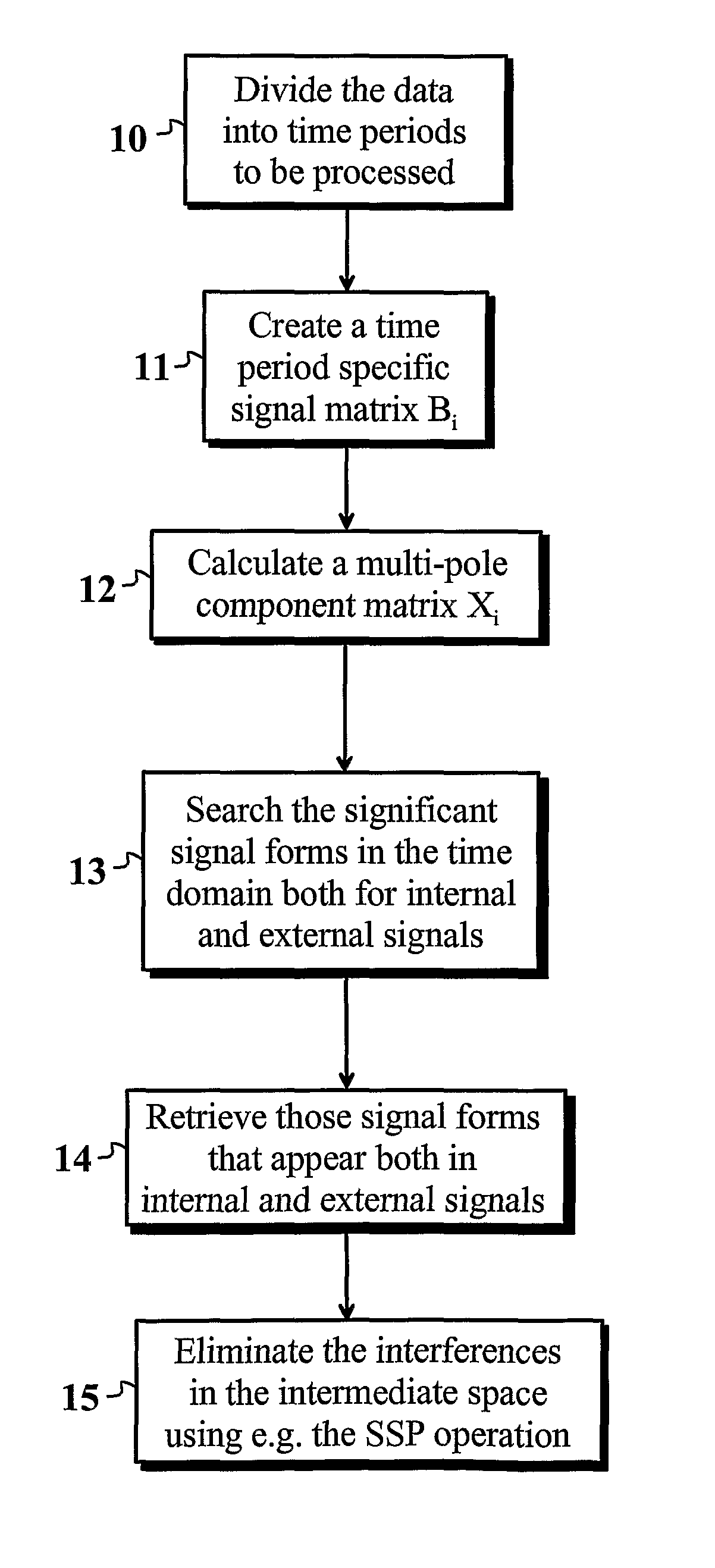
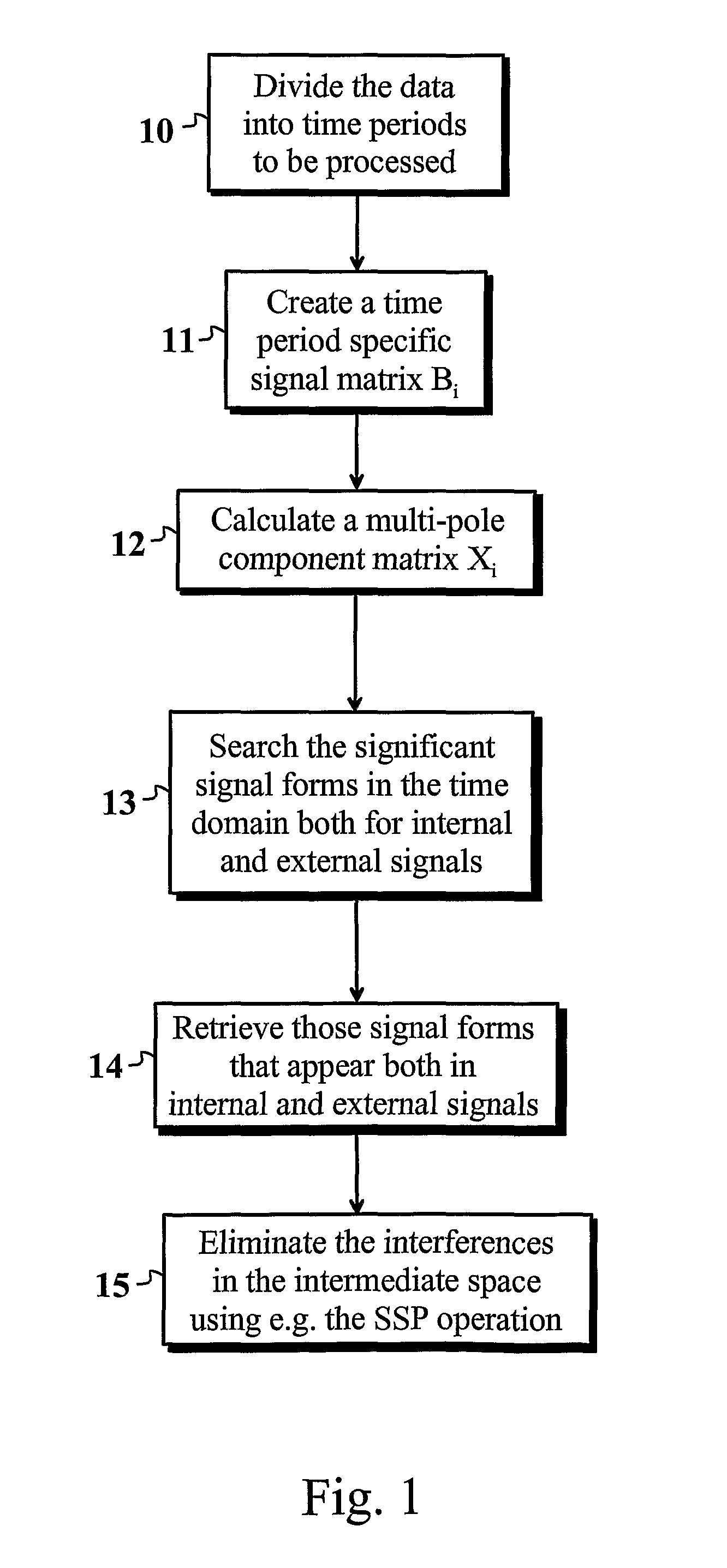
[0028]In the following section, one preferred embodiment of the present invention is shown. In this connection, reference is made to the flow chart shown in FIG. 1. In this mode of carrying out the invention, a mathematical SSS reconstruction of the measured data is performed. The reconstruction finds out both the internal and external multi-pole components. For interference sources that are disposed very close to the sensors, i.e. for those that are disposed in the so-called intermediate space, holds true that they cause signal components both to the external and internal multi-pole components. The interferences in the intermediate space that were found out can be filtered out using a mathematical operation.

[0029]At first, the data is divided into suitable periods of time 10, which are processed separately. The periods of time shall be of suitable length to ensure statistical reliability; and, for example, in the MEG, the length should be at least some tens of milliseconds. In part...


PUM


Abstract

The present invention recognises and eliminates from a biomagnetic measurement signal interferences whose source is disposed in the direct vicinity of an object being measured. The invention utilises the SSS method that can be used to separate from one another the signals associated with the internal and external sources of a set of measurement sensors by calculating two series developments. The sources to be examined in the invention and disposed in the so-called intermediate space produce a component to both of the developments, and can, therefore, be detected by means of an analysis to be performed in a time domain. This division into components can be made using the Principal Component Analysis (PCA), the Independent Component Analysis (ICA) or the Singular Value Decomposition. Finally, the clarified interferences in the intermediate space can be eliminated from the measured signal using, for example, the linear algebraic orthogonal projection.

Description

FIELD OF THE INVENTION[0001]The present invention relates to a novel and advanced method for eliminating from electromagnetic multi-channel measurements such interference signals whose source is disposed very close to the object being measured. In particular, the present invention concerns a novel method for eliminating from multi-channel magnetoencephalographic (MEG) measurements interference signals whose source is disposed at least partly in the region of a patient's head or neck.BACKGROUND OF THE INVENTION[0002]A device that measures weak biomagnetic signals is very susceptible to the influence of the strong magnetic interferences in its operational environment. This is due to the fact that compared to the biomagnetic signals being measured, the interference signals are even ten million times bigger. Furthermore, the implementation of the interference suppression is made more difficult because the region to be shielded from magnetic interferences is relatively large, tens of cen...

Claims


Application Information

Patent Timeline
Patent Type & Authority Patents(United States)
IPC IPC(8): G01R29/08A61B5/24A61B5/05G01R33/025
CPCG01R33/025A61B5/04008A61B5/245
Inventor TAULU, SAMUSIMOLA, JUHA
Owner MEGIN OY
Why Eureka
Try Eureka